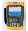
Fluke 192, 196, and 199 Scopemeter Datasheet
Page 1
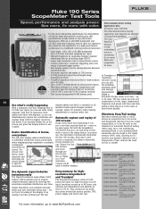
...time anomaly flash by on 100 screens screen. FLUKE-196C/003S ScopeMeter 100 MHz color with SCC kit FLUKE-199C/003 ScopeMeter 200 MHz color FLUKE-199C/003S ScopeMeter 200 MHz color with SCC kit For more with SCC kit waveforms. used as if you can "freeze" the last ...display update rate for you to 48 hours, and FLUKE-196B/003S ScopeMeter 100 MHz B/W with SCC kit FLUKE-199B/003 ScopeMeter 200 MHz B/W FLUKE-199B/003S ScopeMeter 200 MHz B/W with SCC kit FLUKE-196C/003 ScopeMeter 100 MHz color Digital Persistence uses multiple intensity levels and user selectable decay time -...
...time anomaly flash by on 100 screens screen. FLUKE-196C/003S ScopeMeter 100 MHz color with SCC kit FLUKE-199C/003 ScopeMeter 200 MHz color FLUKE-199C/003S ScopeMeter 200 MHz color with SCC kit For more with SCC kit waveforms. used as if you can "freeze" the last ...display update rate for you to 48 hours, and FLUKE-196B/003S ScopeMeter 100 MHz B/W with SCC kit FLUKE-199B/003 ScopeMeter 200 MHz B/W FLUKE-199B/003S ScopeMeter 200 MHz B/W with SCC kit FLUKE-196C/003 ScopeMeter 100 MHz color Digital Persistence uses multiple intensity levels and user selectable decay time -...

FE 192,196,199 C Users Manual
Page 3
... will operate substantially in accordance with a description of the difficulty, postage and insurance prepaid (FOB Destination), to every buyer. Fluke assumes no authority to extend a greater or different warranty on the date of repair costs and obtain authorization before commencing the...abnormal conditions of operation or handling. Fluke's warranty obligation is limited, at Fluke's option, to refund of the purchase price, free of charge repair, or replacement of a defective product which , in material and workmanship under normal use and service. Following warranty repair, the...
... will operate substantially in accordance with a description of the difficulty, postage and insurance prepaid (FOB Destination), to every buyer. Fluke assumes no authority to extend a greater or different warranty on the date of repair costs and obtain authorization before commencing the...abnormal conditions of operation or handling. Fluke's warranty obligation is limited, at Fluke's option, to refund of the purchase price, free of charge repair, or replacement of a defective product which , in material and workmanship under normal use and service. Following warranty repair, the...

FE 192,196,199 C Users Manual
Page 4
SERVICE CENTERS To locate an authorized service center, visit us on the World Wide Web: http://www.fluke.com or call Fluke using any of the phone numbers listed below: +1-888-993-5853 in Europe +1-425-446-5500 from other countries and Canada +31-40-2675200 in U.S.A.
SERVICE CENTERS To locate an authorized service center, visit us on the World Wide Web: http://www.fluke.com or call Fluke using any of the phone numbers listed below: +1-888-993-5853 in Europe +1-425-446-5500 from other countries and Canada +31-40-2675200 in U.S.A.

FE 192,196,199 C Users Manual
Page 5
Fail Testing (C versions only 24 i Table of Contents Chapter Title Page Unpacking the Test Tool Kit 2 Safety Information: Read First 4 1 Using The Scope...7 Powering the Test Tool 7 Resetting the Test Tool 8 Navigating a Menu ...9 Hiding Key Labels and Menus 10 Input Connections ...10 Making Scope Connections 11 Displaying an Unknown Signal with Connect-and-View 12 Making Automatic Scope Measurements 13 Freezing the Screen...14 Using Average, Persistence and Glitch Capture 15 Acquiring Waveforms...18 Pass -
Fail Testing (C versions only 24 i Table of Contents Chapter Title Page Unpacking the Test Tool Kit 2 Safety Information: Read First 4 1 Using The Scope...7 Powering the Test Tool 7 Resetting the Test Tool 8 Navigating a Menu ...9 Hiding Key Labels and Menus 10 Input Connections ...10 Making Scope Connections 11 Displaying an Unknown Signal with Connect-and-View 12 Making Automatic Scope Measurements 13 Freezing the Screen...14 Using Average, Persistence and Glitch Capture 15 Acquiring Waveforms...18 Pass -

FE 192,196,199 C Users Manual
Page 6
Fluke 192B - 196B/C - 199B/C Users Manual Analyzing Waveforms ...25 2 Using The Multimeter 27 Making Meter Connections 27 Making Multimeter Measurements 28 Freezing the Readings 31 Selecting Auto/Manual Ranges 31 Making Relative Measurements 32 3 Using The Recorder Functions 33 Opening the Recorder Main Menu... Over Time (TrendPlot 34 Recording Scope Waveforms In Deep Memory (Scope Record 37 Analyzing a TrendPlot or Scope Record 40 4 Using Replay, Zoom and Cursors 41 Replaying the 100 Most Recent Scope Screens 41 Zooming in on a Waveform 44 Making Cursor Measurements...
Fluke 192B - 196B/C - 199B/C Users Manual Analyzing Waveforms ...25 2 Using The Multimeter 27 Making Meter Connections 27 Making Multimeter Measurements 28 Freezing the Readings 31 Selecting Auto/Manual Ranges 31 Making Relative Measurements 32 3 Using The Recorder Functions 33 Opening the Recorder Main Menu... Over Time (TrendPlot 34 Recording Scope Waveforms In Deep Memory (Scope Record 37 Analyzing a TrendPlot or Scope Record 40 4 Using Replay, Zoom and Cursors 41 Replaying the 100 Most Recent Scope Screens 41 Zooming in on a Waveform 44 Making Cursor Measurements...
FE 192,196,199 C Users Manual
Page 7
Contents (continued) Triggering on Video Signals 59 Triggering on Pulses ...61 6 Using Memory, PC and Printer 65 Saving and Recalling ...65 Documenting Screens...69 7 Tips ...73 Using the Standard Accessories 73 Using the Independently Floating Isolated Inputs 75 Using the Tilt Stand...77 Resetting the Test Tool 77 Suppressing Key Labels and Menu's 77 Changing...
Contents (continued) Triggering on Video Signals 59 Triggering on Pulses ...61 6 Using Memory, PC and Printer 65 Saving and Recalling ...65 Documenting Screens...69 7 Tips ...73 Using the Standard Accessories 73 Using the Independently Floating Isolated Inputs 75 Using the Tilt Stand...77 Resetting the Test Tool 77 Suppressing Key Labels and Menu's 77 Changing...

FE 192,196,199 C Users Manual
Page 9
Lelyweg 1 7602 EA Almelo The Netherlands Statement of Conformity for measurements and laboratory use -EMC requirements- Declaration of Conformity Based on test results using appropriate standards, the product is indicated by the symbol , i.e. "Conformité Europé...the Test Tool Kit Sample tests Standards used: EN 61010.1 : 2001 Safety Requirements for Electrical Equipment for Measurement, Control, and Laboratory Use EN-IEC61326-1 (1997) Electrical equipment for Fluke 192B - 196B/C - 199B/C ScopeMeter® test tools Manufacturer Fluke Industrial B.V. This Conformity is in ...
Lelyweg 1 7602 EA Almelo The Netherlands Statement of Conformity for measurements and laboratory use -EMC requirements- Declaration of Conformity Based on test results using appropriate standards, the product is indicated by the symbol , i.e. "Conformité Europé...the Test Tool Kit Sample tests Standards used: EN 61010.1 : 2001 Safety Requirements for Electrical Equipment for Measurement, Control, and Laboratory Use EN-IEC61326-1 (1997) Electrical equipment for Fluke 192B - 196B/C - 199B/C ScopeMeter® test tools Manufacturer Fluke Industrial B.V. This Conformity is in ...

FE 192,196,199 C Users Manual
Page 12
A "Warning" identifies conditions and actions that may damage the test tool. Fluke 192B - 196B/C - 199B/C Users Manual Safety Information: Read First Carefully read the following international symbols are used on the test tool and in this manual: See explanation in manual Double Insulation (...233;enne Safety Approval Alternating Current 4 Warning To avoid electrical shock or fire: • Use only the Fluke power supply, Model BC190 (Battery Charger / Power Adapter). • Before use check that the selected/indicated range on the BC190 matches the local line power voltage and ...
A "Warning" identifies conditions and actions that may damage the test tool. Fluke 192B - 196B/C - 199B/C Users Manual Safety Information: Read First Carefully read the following international symbols are used on the test tool and in this manual: See explanation in manual Double Insulation (...233;enne Safety Approval Alternating Current 4 Warning To avoid electrical shock or fire: • Use only the Fluke power supply, Model BC190 (Battery Charger / Power Adapter). • Before use check that the selected/indicated range on the BC190 matches the local line power voltage and ...

FE 192,196,199 C Users Manual
Page 13
... above the rating of more than 4800 VA: • Use only insulated voltage probes, test leads and adapters supplied with the test tool, or indicated by Fluke as V dc for appliances and portable equipment. 5 Use caution when using 1:1 test leads because the probe tip voltage will be directly... transmitted to the test tool. • Do not use exposed metal BNC or banana plug connectors. • ...
... above the rating of more than 4800 VA: • Use only insulated voltage probes, test leads and adapters supplied with the test tool, or indicated by Fluke as V dc for appliances and portable equipment. 5 Use caution when using 1:1 test leads because the probe tip voltage will be directly... transmitted to the test tool. • Do not use exposed metal BNC or banana plug connectors. • ...
FE 192,196,199 C Users Manual
Page 14
...Vrms CAT II and 600 Vrms CAT III above earth ground for mechanical damage and replace damaged test leads! Fluke 192B - 196B/C - 199B/C Users Manual The terms 'Isolated' or 'Electrically floating' are used in this manual to indicate a measurement in a manner not specified may impair the protection provided by the..., the test tool fails to a voltage different from the line power. The isolated input connectors have no exposed metal and are Impaired Use of the test tool in which the test tool input BNC or banana jack is connected to perform the intended measurements or shows visible damage...
...Vrms CAT II and 600 Vrms CAT III above earth ground for mechanical damage and replace damaged test leads! Fluke 192B - 196B/C - 199B/C Users Manual The terms 'Isolated' or 'Electrically floating' are used in this manual to indicate a measurement in a manner not specified may impair the protection provided by the..., the test tool fails to a voltage different from the line power. The isolated input connectors have no exposed metal and are Impaired Use of the test tool in which the test tool input BNC or banana jack is connected to perform the intended measurements or shows visible damage...

FE 192,196,199 C Users Manual
Page 15
... Scope Figure 2. Turn the test tool on with the on using battery power. The test tool powers up in Figure 2to power the test tool from a standard ac outlet. About this Chapter This chapter provides a step-...by-step introduction to the scope functions of the scope functions but gives basic examples to show how to use the menus and perform basic operations. Powering the Test Tool 7 See Chapter 8 for instructions on /off key. Powering the Test Tool Follow the procedure (steps...
... Scope Figure 2. Turn the test tool on with the on using battery power. The test tool powers up in Figure 2to power the test tool from a standard ac outlet. About this Chapter This chapter provides a step-...by-step introduction to the scope functions of the scope functions but gives basic examples to show how to use the menus and perform basic operations. Powering the Test Tool 7 See Chapter 8 for instructions on /off key. Powering the Test Tool Follow the procedure (steps...

FE 192,196,199 C Users Manual
Page 17
...Press the ENTER key until you to check the labels without changing the settings. 9 This menu is displayed at the bottom of the screen. 1 Using The Scope Navigating a Menu Figure 4. Note Repeatedly pressing lets you exit the menu. Subsequently follow steps 1 through a menu without affecting your settings. ...2 Open the Waveform Options menu. Basic Navigation 3a Use the blue arrow keys to highlight the item. 3b Press the blue ENTER key to display the labels that define the present...
...Press the ENTER key until you to check the labels without changing the settings. 9 This menu is displayed at the bottom of the screen. 1 Using The Scope Navigating a Menu Figure 4. Note Repeatedly pressing lets you exit the menu. Subsequently follow steps 1 through a menu without affecting your settings. ...2 Open the Waveform Options menu. Basic Navigation 3a Use the blue arrow keys to highlight the item. 3b Press the blue ENTER key to display the labels that define the present...
FE 192,196,199 C Users Manual
Page 18
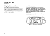
... MENU key to hide any key label or menu. Figure 5. Use the two BNC jack inputs for scope measurements, and the two banana jack inputs for meter measurements. Measurement Connections 10 Isolated input architecture allows independent floating measurements with each input. Fluke 192B - 196B/C - 199B/C Users Manual Hiding Key Labels and Menus...
... MENU key to hide any key label or menu. Figure 5. Use the two BNC jack inputs for scope measurements, and the two banana jack inputs for meter measurements. Measurement Connections 10 Isolated input architecture allows independent floating measurements with each input. Fluke 192B - 196B/C - 199B/C Users Manual Hiding Key Labels and Menus...
FE 192,196,199 C Users Manual
Page 19
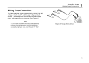
Connect the short ground leads of each voltage probe to its own reference potential. (See Figure 6.) Note To maximally benefit from having independently isolated floating inputs and to input B. Scope Connections 11 Making Scope Connections To make dual input scope measurements, connect the red voltage probe to input A, and the gray voltage probe to avoid problems caused by improper use, read Chapter 7: "Tips". 1 Using The Scope Making Scope Connections Figure 6.
Connect the short ground leads of each voltage probe to its own reference potential. (See Figure 6.) Note To maximally benefit from having independently isolated floating inputs and to input B. Scope Connections 11 Making Scope Connections To make dual input scope measurements, connect the red voltage probe to input A, and the gray voltage probe to avoid problems caused by improper use, read Chapter 7: "Tips". 1 Using The Scope Making Scope Connections Figure 6.
FE 192,196,199 C Users Manual
Page 20
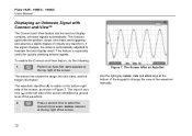
...range again. If the signal changes, the setup is visible on the bottom right side of the screen. Figure 7. The Screen After an Auto Set Use the light-gray RANGE, TIME and MOVE keys at the top right of the screen, as shown in Figure 7. This feature is especially... useful for quickly checking several signals. AUTO appears at the bottom of virtually any waveform. Fluke 192B - 196B/C - 199B/C Users Manual Displaying an Unknown Signal with Connect-and-View™ The Connect-and-...
...range again. If the signal changes, the setup is visible on the bottom right side of the screen. Figure 7. The Screen After an Auto Set Use the light-gray RANGE, TIME and MOVE keys at the top right of the screen, as shown in Figure 7. This feature is especially... useful for quickly checking several signals. AUTO appears at the bottom of virtually any waveform. Fluke 192B - 196B/C - 199B/C Users Manual Displaying an Unknown Signal with Connect-and-View™ The Connect-and-...
FE 192,196,199 C Users Manual
Page 21
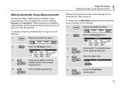
... of the screen displays the Hz measurement. (See Figure 8.) To choose also a Peak-Peak measurement for input A, do the following : 1 Display the SCOPE key labels. 1 Using The Scope Making Automatic Scope Measurements Observe that the top left of automatic scope measurements. These readings are selectable independently, and the measurements can display...
... of the screen displays the Hz measurement. (See Figure 8.) To choose also a Peak-Peak measurement for input A, do the following : 1 Display the SCOPE key labels. 1 Using The Scope Making Automatic Scope Measurements Observe that the top left of automatic scope measurements. These readings are selectable independently, and the measurements can display...

FE 192,196,199 C Users Manual
Page 23
... functions to suppress random or uncorrelated noise in the waveform without smoothing are shown in Figure 9. 3 Jump to open the Average Factors menu Figure 9. Using Average, Persistence and Glitch Capture Using Average for Smoothing Waveforms To smooth the waveform, do the following: 1 Display the SCOPE key labels. 2 Open the Waveform Options menu...
... functions to suppress random or uncorrelated noise in the waveform without smoothing are shown in Figure 9. 3 Jump to open the Average Factors menu Figure 9. Using Average, Persistence and Glitch Capture Using Average for Smoothing Waveforms To smooth the waveform, do the following: 1 Display the SCOPE key labels. 2 Open the Waveform Options menu...
FE 192,196,199 C Users Manual
Page 24
... boundaries of dynamic waveforms (envelope mode). 16 Select Digital Persistence: Off , Envelope: On to Signals observe dynamic waveforms (C-versions only). Fluke 192B - 196B/C - 199B/C Users Manual Using Persistence to Display Waveforms You can use Persistence to observe dynamic signals. 1 Display the SCOPE key labels. 2 Open the Waveform Options menu. 3 Jump to choose your...
... boundaries of dynamic waveforms (envelope mode). 16 Select Digital Persistence: Off , Envelope: On to Signals observe dynamic waveforms (C-versions only). Fluke 192B - 196B/C - 199B/C Users Manual Using Persistence to Display Waveforms You can use Persistence to observe dynamic signals. 1 Display the SCOPE key labels. 2 Open the Waveform Options menu. 3 Jump to choose your...
FE 192,196,199 C Users Manual
Page 25
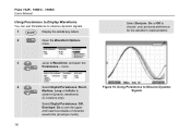
... 8x Tip Glitch capture and average do the following: 1 Display the SCOPE key labels. 2 Open the Waveform Options menu. 1 Using The Scope Using Average, Persistence and Glitch Capture Suppressing High Frequency Noise Switching Glitch Detect to display events (glitches or other asynchronous waveforms) of 50 ns... (nanoseconds) or wider, or you can use this function to Off will suppress the high frequency noise on a waveform, do not affect bandwidth. See Chapter 1: "Working with ...
... 8x Tip Glitch capture and average do the following: 1 Display the SCOPE key labels. 2 Open the Waveform Options menu. 1 Using The Scope Using Average, Persistence and Glitch Capture Suppressing High Frequency Noise Switching Glitch Detect to display events (glitches or other asynchronous waveforms) of 50 ns... (nanoseconds) or wider, or you can use this function to Off will suppress the high frequency noise on a waveform, do not affect bandwidth. See Chapter 1: "Working with ...

FE 192,196,199 C Users Manual
Page 26
... 3 Select Inverted and accept inverted waveform display. 4 Exit the menu. For example, a negative-going waveform which may provide a more meaningful view. Fluke 192B - 196B/C - 199B/C Users Manual Acquiring Waveforms Selecting AC-Coupling After a reset, the test tool is displayed as positive-going waveform is dc-... the ac-coupling icon: . To select ac-coupling, do the following : 1 Display the INPUT A key labels. 2 Highlight AC. Use ac-coupling when you wish to observe a small ac signal that the bottom left of the waveform. 18 Observe that rides on the screen.
... 3 Select Inverted and accept inverted waveform display. 4 Exit the menu. For example, a negative-going waveform which may provide a more meaningful view. Fluke 192B - 196B/C - 199B/C Users Manual Acquiring Waveforms Selecting AC-Coupling After a reset, the test tool is displayed as positive-going waveform is dc-... the ac-coupling icon: . To select ac-coupling, do the following : 1 Display the INPUT A key labels. 2 Highlight AC. Use ac-coupling when you wish to observe a small ac signal that the bottom left of the waveform. 18 Observe that rides on the screen.


