Fluke 192, 196, and 199 Scopemeter Datasheet
Page 1
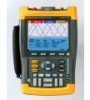
...for trend analysis up to 2.5 GS/s real-time sampling per input record length using the ScopeMeter specifications usually found on 100 screens screen. overlapping can look back in waveforms. Go to specific Cursors can plot the minimum, maximum peak and average measurement (DMM or Automatic Scope) values ... 60 MHz warnings are as 50 ns. Automatic capture and replay of those faults quickly. Now you can be B/W with SCC kit FLUKE-196C/003 ScopeMeter 100 MHz color Digital Persistence uses multiple intensity levels and user selectable decay time - up to 22 days • Up ...
...for trend analysis up to 2.5 GS/s real-time sampling per input record length using the ScopeMeter specifications usually found on 100 screens screen. overlapping can look back in waveforms. Go to specific Cursors can plot the minimum, maximum peak and average measurement (DMM or Automatic Scope) values ... 60 MHz warnings are as 50 ns. Automatic capture and replay of those faults quickly. Now you can be B/W with SCC kit FLUKE-196C/003 ScopeMeter 100 MHz color Digital Persistence uses multiple intensity levels and user selectable decay time - up to 22 days • Up ...

FE 192,196,199 C Users Manual
Page 3
... damages, the limitations and exclusions of this warranty on the date of shipment. Box 9090, Everett, WA 98206-9090 USA, or Fluke Industrial B.V., P.O. Fluke reserves the right to refund of the purchase price, free of charge repair, or replacement of a defective product which , in another.../replacement parts when product purchased in one country is three years for the test tool and one year for its functional specifications for repair in Fluke's opinion, has been misused, altered, neglected or damaged by accident or abnormal conditions of operation or handling. Following repair...
... damages, the limitations and exclusions of this warranty on the date of shipment. Box 9090, Everett, WA 98206-9090 USA, or Fluke Industrial B.V., P.O. Fluke reserves the right to refund of the purchase price, free of charge repair, or replacement of a defective product which , in another.../replacement parts when product purchased in one country is three years for the test tool and one year for its functional specifications for repair in Fluke's opinion, has been misused, altered, neglected or damaged by accident or abnormal conditions of operation or handling. Following repair...
FE 192,196,199 C Users Manual
Page 8
Fluke 192B - 196B/C - 199B/C Users Manual Parts and Accessories 88 Troubleshooting ...93 9 Specifications ...95 Introduction ...95 Dual Input Oscilloscope 96 Automatic Scope Measurements 98 Meter ...102 DMM Measurements on Meter Inputs 102 Recorder ...104 Zoom, Replay and Cursors 105 Miscellaneous ...105 Environmental...107 Safety ...107 10:1 Probe ...109 Electromagnetic Immunity 110 iv
Fluke 192B - 196B/C - 199B/C Users Manual Parts and Accessories 88 Troubleshooting ...93 9 Specifications ...95 Introduction ...95 Dual Input Oscilloscope 96 Automatic Scope Measurements 98 Meter ...102 DMM Measurements on Meter Inputs 102 Recorder ...104 Zoom, Replay and Cursors 105 Miscellaneous ...105 Environmental...107 Safety ...107 10:1 Probe ...109 Electromagnetic Immunity 110 iv

FE 192,196,199 C Users Manual
Page 12
...indicated range on the BC190 matches the local line power voltage and frequency. • For the BC190/808 universal Battery Charger / Power Adapter) only use . Fluke 192B - 196B/C - 199B/C Users Manual Safety Information: Read First Carefully read the following international symbols are more commonly available you might consider using the test... need to be connected to a line cord appropriate for connection to the user. A "Warning" identifies conditions and actions that may damage the test tool. Specific warning and caution statements, where they apply, appear throughout the manual.
...indicated range on the BC190 matches the local line power voltage and frequency. • For the BC190/808 universal Battery Charger / Power Adapter) only use . Fluke 192B - 196B/C - 199B/C Users Manual Safety Information: Read First Carefully read the following international symbols are more commonly available you might consider using the test... need to be connected to a line cord appropriate for connection to the user. A "Warning" identifies conditions and actions that may damage the test tool. Specific warning and caution statements, where they apply, appear throughout the manual.
FE 192,196,199 C Users Manual
Page 63
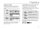
..., do the following: 1 Display the TRIGGER key labels. 2 Open the Trigger Options menu. 3 Open the Trigger on Edge menu. To trigger on rising edges of specific edge trigger settings: 55 Triggering on Edges If the signal is selected, the test tool waits for a trigger. When Single Shot is instable or has...
..., do the following: 1 Display the TRIGGER key labels. 2 Open the Trigger Options menu. 3 Open the Trigger on Edge menu. To trigger on rising edges of specific edge trigger settings: 55 Triggering on Edges If the signal is selected, the test tool waits for a trigger. When Single Shot is instable or has...
FE 192,196,199 C Users Manual
Page 65
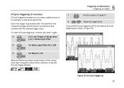
... Figure 30. 6 Set NCycle to On Observe that the key labels at the bottom of the screen have been changed to create a stable picture of specific N-Cycle trigger settings: Figure 30.
... Figure 30. 6 Set NCycle to On Observe that the key labels at the bottom of the screen have been changed to create a stable picture of specific N-Cycle trigger settings: Figure 30.
FE 192,196,199 C Users Manual
Page 67
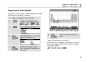
... Signals 6 4 Select Video on Video menu. to open the Trigger on A ... Triggering on Video Signals To trigger on a video signal, first select the standard of specific video trigger settings: 5 Select positive signal polarity for video signals with negative going to measure: 1 Apply a video signal to the red input A. 2 Display the TRIGGER...
... Signals 6 4 Select Video on Video menu. to open the Trigger on A ... Triggering on Video Signals To trigger on a video signal, first select the standard of specific video trigger settings: 5 Select positive signal polarity for video signals with negative going to measure: 1 Apply a video signal to the red input A. 2 Display the TRIGGER...
FE 192,196,199 C Users Manual
Page 68
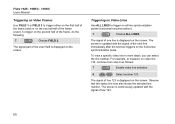
... FIELD 2. Triggering on Video Lines Use ALL LINES to trigger on the screen. Observe that the status line now also shows the selected line number. Fluke 192B - 196B/C - 199B/C Users Manual Triggering on Video Frames Use FIELD 1 or FIELD 2 to trigger either on the first half of the frame (odd) or... on the second half of the frame (even).To trigger on the screen. To view a specific video line in more detail, you can select the line number. The signal part of the even field is continuously updated with the signal of...
... FIELD 2. Triggering on Video Lines Use ALL LINES to trigger on the screen. Observe that the status line now also shows the selected line number. Fluke 192B - 196B/C - 199B/C Users Manual Triggering on Video Frames Use FIELD 1 or FIELD 2 to trigger either on the first half of the frame (odd) or... on the second half of the frame (even).To trigger on the screen. To view a specific video line in more detail, you can select the line number. The signal part of the even field is continuously updated with the signal of...
FE 192,196,199 C Users Manual
Page 69
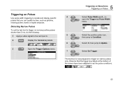
... Pulses 4 Select Pulse Width on A... Detecting Narrow Pulses To set the test tool to trigger on Pulses Use pulse width triggering to isolate and display specific pulses that you can qualify by time, such as glitches, missing pulses, bursts or signal dropouts. Triggering on narrow positive pulses shorter than 5 ms, do...
... Pulses 4 Select Pulse Width on A... Detecting Narrow Pulses To set the test tool to trigger on Pulses Use pulse width triggering to isolate and display specific pulses that you can qualify by time, such as glitches, missing pulses, bursts or signal dropouts. Triggering on narrow positive pulses shorter than 5 ms, do...
FE 192,196,199 C Users Manual
Page 78
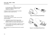
... connect a parallel printer to the OPTICAL PORT of the test tool. (See Figure 37.) Before printing, you must setup the test tool for a specific printer. 70 Figure 36. Fluke 192B - 196B/C - 199B/C Users Manual Note For information about installing and using the FlukeView ScopeMeter software, see the SW90W Users Manual. Connecting a Parallel...
... connect a parallel printer to the OPTICAL PORT of the test tool. (See Figure 37.) Before printing, you must setup the test tool for a specific printer. 70 Figure 36. Fluke 192B - 196B/C - 199B/C Users Manual Note For information about installing and using the FlukeView ScopeMeter software, see the SW90W Users Manual. Connecting a Parallel...

FE 192,196,199 C Users Manual
Page 92
...if the charger is used, the battery indicator at the top of the screen informs you about the condition of the batteries during the weekend. Fluke 192B - 196B/C - 199B/C Users Manual Charging the Batteries At delivery, the NiMH batteries may be empty and must be charged for long ... the allowable ambient temperature given in Figure 47. To charge the batteries and power the instrument, connect the battery charger as shown in the specifications. The battery symbols are typically five minutes of use. To charge the batteries more quickly, turn off ) to trickle charging. 84 Figure ...
...if the charger is used, the battery indicator at the top of the screen informs you about the condition of the batteries during the weekend. Fluke 192B - 196B/C - 199B/C Users Manual Charging the Batteries At delivery, the NiMH batteries may be empty and must be charged for long ... the allowable ambient temperature given in Figure 47. To charge the batteries and power the instrument, connect the battery charger as shown in the specifications. The battery symbols are typically five minutes of use. To charge the batteries more quickly, turn off ) to trickle charging. 84 Figure ...
FE 192,196,199 C Users Manual
Page 94
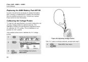
... nearest Fluke center for 10:1 probes. The calibration consists of a high frequency adjustment and a dc calibration for more information. This example shows how to adjust the red and gray voltage probes for 100:1 probes. Calibrating the Voltage Probes To meet full user specifications, you...calibration is already selected, proceed with step 5. 4 Select 10:1, then return. 3 Select Voltage, then jump to replace the battery pack. Fluke 192B - 196B/C - 199B/C Users Manual Replacing the NiMH Battery Pack BP190 Usually it should be necessary to Attenuation. 86 However, if ...
... nearest Fluke center for 10:1 probes. The calibration consists of a high frequency adjustment and a dc calibration for more information. This example shows how to adjust the red and gray voltage probes for 100:1 probes. Calibrating the Voltage Probes To meet full user specifications, you...calibration is already selected, proceed with step 5. 4 Select 10:1, then return. 3 Select Voltage, then jump to replace the battery pack. Fluke 192B - 196B/C - 199B/C Users Manual Replacing the NiMH Battery Pack BP190 Usually it should be necessary to Attenuation. 86 However, if ...
FE 192,196,199 C Users Manual
Page 103
...1010.1-92 (including approval), UL3111-1 (including approval) Safety Requirements for Electrical Equipment for Measurement, Control, and Laboratory Use. Specifications are based on a 1-year calibration cycle. This manual contains information and warnings that could be followed by the equipment. ... procedures. Environmental Data The environmental data mentioned in a safe condition. Chapter 9 Specifications Introduction Performance Characteristics FLUKE guarantees the properties expressed in accordance with the stated tolerance. Use of identical ScopeMeter test tools.
...1010.1-92 (including approval), UL3111-1 (including approval) Safety Requirements for Electrical Equipment for Measurement, Control, and Laboratory Use. Specifications are based on a 1-year calibration cycle. This manual contains information and warnings that could be followed by the equipment. ... procedures. Environmental Data The environmental data mentioned in a safe condition. Chapter 9 Specifications Introduction Performance Characteristics FLUKE guarantees the properties expressed in accordance with the stated tolerance. Use of identical ScopeMeter test tools.
FE 192,196,199 C Users Manual
Page 104
...(±1 %)//15 pF (±2 pF) Max. Input Voltage with 10:1 probe 600 V CAT III; 1000 V CAT II direct (1:1 300 V CAT III (For detailed specifications, see "Safety") Vertical Accuracy 1.5 % + 0.04 range/div) 2 mV/div: ....±(2.5 % + 0.08 range/div) For voltage measurements with 10:1 probe 50...(1:1 5 mV to 120 s/div 20 MS/s Digitizer Resolution 8 bits, separate digitizer for each input Horizontal Maximum Time Base Speed: FLUKE 196B/C, 199B/C 5 ns/div FLUKE 192B 10 ns/div Minimum Time Base Speed (Scope Record) ..... 2 min/div Real Time Sampling Rate (for both inputs simultaneously...
...(±1 %)//15 pF (±2 pF) Max. Input Voltage with 10:1 probe 600 V CAT III; 1000 V CAT II direct (1:1 300 V CAT III (For detailed specifications, see "Safety") Vertical Accuracy 1.5 % + 0.04 range/div) 2 mV/div: ....±(2.5 % + 0.08 range/div) For voltage measurements with 10:1 probe 50...(1:1 5 mV to 120 s/div 20 MS/s Digitizer Resolution 8 bits, separate digitizer for each input Horizontal Maximum Time Base Speed: FLUKE 196B/C, 199B/C 5 ns/div FLUKE 192B 10 ns/div Minimum Time Base Speed (Scope Record) ..... 2 min/div Real Time Sampling Rate (for both inputs simultaneously...
FE 192,196,199 C Users Manual
Page 105
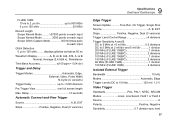
... screen length Max. Delay 12 seconds Automatic Connect-and-View Trigger Source A, B, EXT Slope Positive, Negative, Dual (C versions) 9 Specifications Dual Input Oscilloscope Edge Trigger Screen Update Free Run, On Trigger, Single Shot Source A, B, EXT Slope Positive, Negative, Dual (C...2 mV/div and 5 mV/div ...........1 division 200 MHz (FLUKE 199B/C 1 division 250 MHz (FLUKE 199B/C 2 divisions 100 MHz (FLUKE 196B/C 1 division 150 MHz (FLUKE 196B/C 2 divisions 60 MHz (FLUKE 192B 1 division 100 MHz (FLUKE 192B 2 divisions Isolated External Trigger Bandwidth 10 kHz Modes Automatic, ...
... screen length Max. Delay 12 seconds Automatic Connect-and-View Trigger Source A, B, EXT Slope Positive, Negative, Dual (C versions) 9 Specifications Dual Input Oscilloscope Edge Trigger Screen Update Free Run, On Trigger, Single Shot Source A, B, EXT Slope Positive, Negative, Dual (C...2 mV/div and 5 mV/div ...........1 division 200 MHz (FLUKE 199B/C 1 division 250 MHz (FLUKE 199B/C 2 divisions 100 MHz (FLUKE 196B/C 1 division 150 MHz (FLUKE 196B/C 2 divisions 60 MHz (FLUKE 192B 1 division 100 MHz (FLUKE 192B 2 divisions Isolated External Trigger Bandwidth 10 kHz Modes Automatic, ...
FE 192,196,199 C Users Manual
Page 106
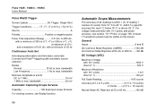
Fluke 192B - 196B/C - 199B/C Users Manual Pulse Width Trigger Screen Update On Trigger, Single Shot Trigger Conditions T, >T, =T (±10 %), ≠T(±10 %) Source A Polarity Positive or ..., or 400 Hz ......>60 dB DC Voltage (VDC) Maximum Voltage with 10:1 probe 1000 V direct (1:1 300 V Maximum Resolution with a minimum of 0.01 div. Add 0.1x (specific accuracy) for each °C below 18 °C or above 28 °C. For voltage measurements with automatic source selection. with a minimum of 300 ns (T) or 500...
Fluke 192B - 196B/C - 199B/C Users Manual Pulse Width Trigger Screen Update On Trigger, Single Shot Trigger Conditions T, >T, =T (±10 %), ≠T(±10 %) Source A Polarity Positive or ..., or 400 Hz ......>60 dB DC Voltage (VDC) Maximum Voltage with 10:1 probe 1000 V direct (1:1 300 V Maximum Resolution with a minimum of 0.01 div. Add 0.1x (specific accuracy) for each °C below 18 °C or above 28 °C. For voltage measurements with automatic source selection. with a minimum of 300 ns (T) or 500...
FE 192,196,199 C Users Manual
Page 107
...) For higher frequencies the instrument's frequency roll off starts affecting accuracy. When possible use DC coupling for low frequencies. Normal Mode DC Rejection 50 dB 9 Specifications Automatic Scope Measurements All accuracies are valid if: • The waveform amplitude is larger than one division • At least 1.5 waveform period is on the...
...) For higher frequencies the instrument's frequency roll off starts affecting accuracy. When possible use DC coupling for low frequencies. Normal Mode DC Rejection 50 dB 9 Specifications Automatic Scope Measurements All accuracies are valid if: • The waveform amplitude is larger than one division • At least 1.5 waveform period is on the...
FE 192,196,199 C Users Manual
Page 109
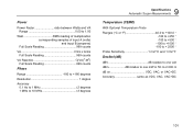
... VA)2-W2) Full Scale Reading 999 counts Phase Range 180 to +180 degrees Resolution 1 degree Accuracy 0.1 Hz to 1 MHz 2 degrees 1 MHz to 10 MHz 3 degrees 9 Specifications Automatic Scope Measurements Temperature (TEMP) With Optional Temperature Probe Ranges (°C or °F 40.0 to +100.0 ° -100 to +250 ° -100 to +500 °...
... VA)2-W2) Full Scale Reading 999 counts Phase Range 180 to +180 degrees Resolution 1 degree Accuracy 0.1 Hz to 1 MHz 2 degrees 1 MHz to 10 MHz 3 degrees 9 Specifications Automatic Scope Measurements Temperature (TEMP) With Optional Temperature Probe Ranges (°C or °F 40.0 to +100.0 ° -100 to +250 ° -100 to +500 °...
FE 192,196,199 C Users Manual
Page 110
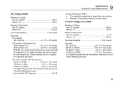
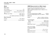
Add 0.1x (specific accuracy) for each °C below 18 °C or above 28 °C. General DC Common Mode Rejection (CMRR 100 dB AC Common Mode Rejection at 50, ... kHz (-3 dB) Input Impedance 1 MΩ (±1 %)//10 pF (±1.5 pF) Max. Fluke 192B - 196B/C - 199B/C Users Manual Meter Meter Input Input Coupling DC Frequency Response DC to 28 °C. Input Voltage 1000 V CAT II 600 V CAT III (For detailed specifications, see "Safety") Meter Functions Ranging Auto, Manual Modes Normal, Relative 102 DMM...
Add 0.1x (specific accuracy) for each °C below 18 °C or above 28 °C. General DC Common Mode Rejection (CMRR 100 dB AC Common Mode Rejection at 50, ... kHz (-3 dB) Input Impedance 1 MΩ (±1 %)//10 pF (±1.5 pF) Max. Fluke 192B - 196B/C - 199B/C Users Manual Meter Meter Input Input Coupling DC Frequency Response DC to 28 °C. Input Voltage 1000 V CAT II 600 V CAT III (For detailed specifications, see "Safety") Meter Functions Ranging Auto, Manual Modes Normal, Relative 102 DMM...
FE 192,196,199 C Users Manual
Page 111
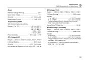
....0 mV, 5.000 V, 50.00 V, 500.0 V, 1100 V Full Scale Reading 5000 counts Accuracy 0.5 % +5 counts) Normal Mode AC Rejection at 50 or 60 Hz ±1 % .... >60 dB 9 Specifications DMM Measurements on Meter Inputs AC Voltage (VAC) Ranges......500.0 mV, 5.000 V, 50.00 V, 500.0 V, 1100 V Full Scale Reading 5000 counts Accuracy 15 Hz to...
....0 mV, 5.000 V, 50.00 V, 500.0 V, 1100 V Full Scale Reading 5000 counts Accuracy 0.5 % +5 counts) Normal Mode AC Rejection at 50 or 60 Hz ±1 % .... >60 dB 9 Specifications DMM Measurements on Meter Inputs AC Voltage (VAC) Ranges......500.0 mV, 5.000 V, 50.00 V, 500.0 V, 1100 V Full Scale Reading 5000 counts Accuracy 15 Hz to...
