Fluke 192, 196, and 199 Scopemeter Datasheet
Page 1
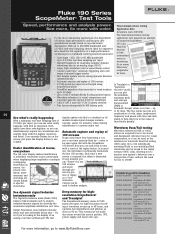
...makes identification the last 100 screens. Not with SCC kit waveforms. used as if you can look back in time with SCC kit FLUKE-196C/003 ScopeMeter 100 MHz color Digital Persistence uses multiple intensity levels and user selectable decay time - and scroll screen color through pic- Deep...dynamic behavior 190 color Pass/Fail function to find anomalies and to 22 days. This continuous roll mode also stores events like on an analog scope (190C) • Large, high-resolution color or monochrome screen • Connect-and-View™ automatic triggering and a full range of ...
...makes identification the last 100 screens. Not with SCC kit waveforms. used as if you can look back in time with SCC kit FLUKE-196C/003 ScopeMeter 100 MHz color Digital Persistence uses multiple intensity levels and user selectable decay time - and scroll screen color through pic- Deep...dynamic behavior 190 color Pass/Fail function to find anomalies and to 22 days. This continuous roll mode also stores events like on an analog scope (190C) • Large, high-resolution color or monochrome screen • Connect-and-View™ automatic triggering and a full range of ...
FE 192,196,199 C Users Manual
Page 5
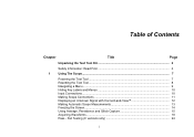
Fail Testing (C versions only 24 i Table of Contents Chapter Title Page Unpacking the Test Tool Kit 2 Safety Information: Read First 4 1 Using The Scope...7 Powering the Test Tool 7 Resetting the Test Tool 8 Navigating a Menu ...9 Hiding Key Labels and Menus 10 Input Connections ...10 Making Scope Connections 11 Displaying an Unknown Signal with Connect-and-View 12 Making Automatic Scope Measurements 13 Freezing the Screen...14 Using Average, Persistence and Glitch Capture 15 Acquiring Waveforms...18 Pass -
Fail Testing (C versions only 24 i Table of Contents Chapter Title Page Unpacking the Test Tool Kit 2 Safety Information: Read First 4 1 Using The Scope...7 Powering the Test Tool 7 Resetting the Test Tool 8 Navigating a Menu ...9 Hiding Key Labels and Menus 10 Input Connections ...10 Making Scope Connections 11 Displaying an Unknown Signal with Connect-and-View 12 Making Automatic Scope Measurements 13 Freezing the Screen...14 Using Average, Persistence and Glitch Capture 15 Acquiring Waveforms...18 Pass -

FE 192,196,199 C Users Manual
Page 6
Fluke 192B - 196B/C - 199B/C Users Manual Analyzing Waveforms ...25 2 Using The Multimeter 27 Making Meter Connections 27 Making Multimeter Measurements 28 Freezing the Readings 31 Selecting ... 33 Opening the Recorder Main Menu 33 Plotting Measurements Over Time (TrendPlot 34 Recording Scope Waveforms In Deep Memory (Scope Record 37 Analyzing a TrendPlot or Scope Record 40 4 Using Replay, Zoom and Cursors 41 Replaying the 100 Most Recent Scope Screens 41 Zooming in on a Waveform 44 Making Cursor Measurements 46 5 Triggering on Waveforms...
Fluke 192B - 196B/C - 199B/C Users Manual Analyzing Waveforms ...25 2 Using The Multimeter 27 Making Meter Connections 27 Making Multimeter Measurements 28 Freezing the Readings 31 Selecting ... 33 Opening the Recorder Main Menu 33 Plotting Measurements Over Time (TrendPlot 34 Recording Scope Waveforms In Deep Memory (Scope Record 37 Analyzing a TrendPlot or Scope Record 40 4 Using Replay, Zoom and Cursors 41 Replaying the 100 Most Recent Scope Screens 41 Zooming in on a Waveform 44 Making Cursor Measurements 46 5 Triggering on Waveforms...

FE 192,196,199 C Users Manual
Page 8
Fluke 192B - 196B/C - 199B/C Users Manual Parts and Accessories 88 Troubleshooting ...93 9 Specifications ...95 Introduction ...95 Dual Input Oscilloscope 96 Automatic Scope Measurements 98 Meter ...102 DMM Measurements on Meter Inputs 102 Recorder ...104 Zoom, Replay and Cursors 105 Miscellaneous ...105 Environmental...107 Safety ...107 10:1 Probe ...109 Electromagnetic Immunity 110 iv
Fluke 192B - 196B/C - 199B/C Users Manual Parts and Accessories 88 Troubleshooting ...93 9 Specifications ...95 Introduction ...95 Dual Input Oscilloscope 96 Automatic Scope Measurements 98 Meter ...102 DMM Measurements on Meter Inputs 102 Recorder ...104 Zoom, Replay and Cursors 105 Miscellaneous ...105 Environmental...107 Safety ...107 10:1 Probe ...109 Electromagnetic Immunity 110 iv

FE 192,196,199 C Users Manual
Page 15
... with the on using battery power. The test tool powers up in Figure 2to power the test tool from a standard ac outlet. Chapter 1 Using The Scope Figure 2. Powering the Test Tool 7 See Chapter 8 for instructions on /off key. The introduction does not cover all of the capabilities of the...
... with the on using battery power. The test tool powers up in Figure 2to power the test tool from a standard ac outlet. Chapter 1 Using The Scope Figure 2. Powering the Test Tool 7 See Chapter 8 for instructions on /off key. The introduction does not cover all of the capabilities of the...

FE 192,196,199 C Users Manual
Page 17
This menu is displayed at the bottom of the screen. 1 Using The Scope Navigating a Menu Figure 4. Basic Navigation 3a Use the blue arrow keys to highlight the item. 3b Press the blue ENTER key to accept the selection. 4 ... the labels for the four blue function keys at the bottom of the screen. Subsequently follow steps 1 through 4 to open the scope menu and to choose an item. 1 Press the SCOPE key to step through a menu without affecting your settings. 2 Open the Waveform Options menu. Note Repeatedly pressing lets you exit the...
This menu is displayed at the bottom of the screen. 1 Using The Scope Navigating a Menu Figure 4. Basic Navigation 3a Use the blue arrow keys to highlight the item. 3b Press the blue ENTER key to accept the selection. 4 ... the labels for the four blue function keys at the bottom of the screen. Subsequently follow steps 1 through 4 to open the scope menu and to choose an item. 1 Press the SCOPE key to step through a menu without affecting your settings. 2 Open the Waveform Options menu. Note Repeatedly pressing lets you exit the...
FE 192,196,199 C Users Manual
Page 18
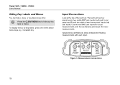
... input B) and two safety 4-mm banana jack inputs (red and black). Measurement Connections 10 Isolated input architecture allows independent floating measurements with each input. Fluke 192B - 196B/C - 199B/C Users Manual Hiding Key Labels and Menus You can hide a menu or key label at the top of the yellow... menu keys, e.g. Figure 5. To display menus or key labels, press one of the test tool. the SCOPE key. Use the two BNC jack inputs for scope measurements, and the two banana jack inputs for meter measurements. Input Connections Look at any time: Press the CLEAR MENU ...
... input B) and two safety 4-mm banana jack inputs (red and black). Measurement Connections 10 Isolated input architecture allows independent floating measurements with each input. Fluke 192B - 196B/C - 199B/C Users Manual Hiding Key Labels and Menus You can hide a menu or key label at the top of the yellow... menu keys, e.g. Figure 5. To display menus or key labels, press one of the test tool. the SCOPE key. Use the two BNC jack inputs for scope measurements, and the two banana jack inputs for meter measurements. Input Connections Look at any time: Press the CLEAR MENU ...
FE 192,196,199 C Users Manual
Page 19
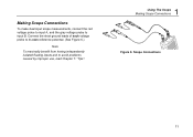
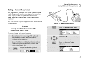
Connect the short ground leads of each voltage probe to its own reference potential. (See Figure 6.) Note To maximally benefit from having independently isolated floating inputs and to input B. Scope Connections 11 Making Scope Connections To make dual input scope measurements, connect the red voltage probe to input A, and the gray voltage probe to avoid problems caused by improper use, read Chapter 7: "Tips". 1 Using The Scope Making Scope Connections Figure 6.
Connect the short ground leads of each voltage probe to its own reference potential. (See Figure 6.) Note To maximally benefit from having independently isolated floating inputs and to input B. Scope Connections 11 Making Scope Connections To make dual input scope measurements, connect the red voltage probe to input A, and the gray voltage probe to avoid problems caused by improper use, read Chapter 7: "Tips". 1 Using The Scope Making Scope Connections Figure 6.
FE 192,196,199 C Users Manual
Page 21
... input A or input B waveform To choose a frequency measurement for input A, do the following: 1 Display the SCOPE key labels. 1 Using The Scope Making Automatic Scope Measurements Observe that the highlight jumps to the measurements field. 4 Open the PEAK menu. 3 Select on B. The... measurement. 13 These readings are selectable independently, and the measurements can display two numeric readings: READING 1 and READING 2. Making Automatic Scope Measurements The test tool offers a wide range of the screen displays the Hz measurement. (See Figure 8.) To choose also a Peak...
... input A or input B waveform To choose a frequency measurement for input A, do the following: 1 Display the SCOPE key labels. 1 Using The Scope Making Automatic Scope Measurements Observe that the highlight jumps to the measurements field. 4 Open the PEAK menu. 3 Select on B. The... measurement. 13 These readings are selectable independently, and the measurements can display two numeric readings: READING 1 and READING 2. Making Automatic Scope Measurements The test tool offers a wide range of the screen displays the Hz measurement. (See Figure 8.) To choose also a Peak...
FE 192,196,199 C Users Manual
Page 22
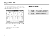
HOLD appears at any time. 1 Freeze the screen. Hz and V peak-peak as Scope Readings Note The B versions do not provide Vpwm measurements. 14 Freezing the Screen You can freeze the screen (all readings and waveforms) at the right of the reading area. 2 Resume your measurement. Figure 8. Note that the Peak-Peak reading for input B appears next to the input A frequency reading at the top of the screen. Fluke 192B - 196B/C - 199B/C Users Manual Figure 8 shows an example of the screen.
HOLD appears at any time. 1 Freeze the screen. Hz and V peak-peak as Scope Readings Note The B versions do not provide Vpwm measurements. 14 Freezing the Screen You can freeze the screen (all readings and waveforms) at the right of the reading area. 2 Resume your measurement. Figure 8. Note that the Peak-Peak reading for input B appears next to the input A frequency reading at the top of the screen. Fluke 192B - 196B/C - 199B/C Users Manual Figure 8 shows an example of the screen.

FE 192,196,199 C Users Manual
Page 23
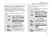
... Using Average, Persistence and Glitch Capture Using Average for Smoothing Waveforms To smooth the waveform, do the following: 1 Display the SCOPE key labels. 2 Open the Waveform Options menu. 1 Using The Scope Using Average, Persistence and Glitch Capture 5 Select Average 64.This averages the outcomes of bandwidth. Waveform samples with and without loss...
... Using Average, Persistence and Glitch Capture Using Average for Smoothing Waveforms To smooth the waveform, do the following: 1 Display the SCOPE key labels. 2 Open the Waveform Options menu. 1 Using The Scope Using Average, Persistence and Glitch Capture 5 Select Average 64.This averages the outcomes of bandwidth. Waveform samples with and without loss...
FE 192,196,199 C Users Manual
Page 24
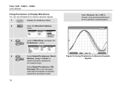
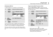
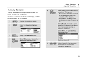
...: Short, Figure 10. Select Digital Persistence: Off , Envelope: On to Waveform: and open the Persistence... Fluke 192B - 196B/C - 199B/C Users Manual Using Persistence to Display Waveforms You can use Persistence to observe dynamic signals. 1 Display the SCOPE key labels. 2 Open the Waveform Options menu. 3 Jump to see the upper and lower boundaries...
...: Short, Figure 10. Select Digital Persistence: Off , Envelope: On to Waveform: and open the Persistence... Fluke 192B - 196B/C - 199B/C Users Manual Using Persistence to Display Waveforms You can use Persistence to observe dynamic signals. 1 Display the SCOPE key labels. 2 Open the Waveform Options menu. 3 Jump to see the upper and lower boundaries...
FE 192,196,199 C Users Manual
Page 25
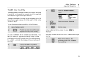
...the Average menu 4 Select Factor : 8x Tip Glitch capture and average do the following: 1 Display the SCOPE key labels. 2 Open the Waveform Options menu. 1 Using The Scope Using Average, Persistence and Glitch Capture Suppressing High Frequency Noise Switching Glitch Detect to Off will suppress the high...In the 2 mV/div range you select the 2 mV/div range Glitch Detect will suppress the noise even more. 1 Display the SCOPE key labels. 2 Open the Waveform Options menu. 3 Select Glitch Detect: On 4 Exit the menu. Further noise suppression is possible with Noisy Waveforms"....
...the Average menu 4 Select Factor : 8x Tip Glitch capture and average do the following: 1 Display the SCOPE key labels. 2 Open the Waveform Options menu. 1 Using The Scope Using Average, Persistence and Glitch Capture Suppressing High Frequency Noise Switching Glitch Detect to Off will suppress the high...In the 2 mV/div range you select the 2 mV/div range Glitch Detect will suppress the noise even more. 1 Display the SCOPE key labels. 2 Open the Waveform Options menu. 3 Select Glitch Detect: On 4 Exit the menu. Further noise suppression is possible with Noisy Waveforms"....
FE 192,196,199 C Users Manual
Page 27
... left of the screen) An Auto Set will turn off the variable input sensitivity. Selecting Variable will increase). 3 Display the INPUT A key labels. 1 Using The Scope Acquiring Waveforms 4 Open the Input A Options... You can be increased up to 2.5 times, for example to adjust the input A sensitivity continuously, for example between 10...
... left of the screen) An Auto Set will turn off the variable input sensitivity. Selecting Variable will increase). 3 Display the INPUT A key labels. 1 Using The Scope Acquiring Waveforms 4 Open the Input A Options... You can be increased up to 2.5 times, for example to adjust the input A sensitivity continuously, for example between 10...
FE 192,196,199 C Users Manual
Page 28
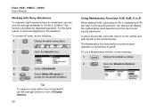
... the horizontal axis. Tip To suppress noise without loss of bandwidth, use a Mathematics function, do the following : 1 Display the SCOPE key labels. 2 Open the Waveform Options menu. This function smoothes the displayed waveform. Fluke 192B - 196B/C - 199B/C Users Manual Working with input A on the vertical axis and input B on the waveform. The...
... the horizontal axis. Tip To suppress noise without loss of bandwidth, use a Mathematics function, do the following : 1 Display the SCOPE key labels. 2 Open the Waveform Options menu. This function smoothes the displayed waveform. Fluke 192B - 196B/C - 199B/C Users Manual Working with input A on the vertical axis and input B on the waveform. The...
FE 192,196,199 C Users Manual
Page 29
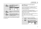
...range of the mathematical result is recommended to the sensitivity range of the least sensitive input divided by the scale factor. 1 Using The Scope Acquiring Waveforms Using Mathematics Function Spectrum (FFT, C Versions) The Spectrum function shows the spectral content of cycles Selecting Hanning, Hamming or...will automatically adapt the part of side-lobes (leakage) it is equal to use the Spectrum function, do the following: 1 Display the SCOPE key labels. 2 Open the Waveform Options menu. 21 3 Jump to transform the amplitude waveform from the time domain into the frequency ...
...range of the mathematical result is recommended to the sensitivity range of the least sensitive input divided by the scale factor. 1 Using The Scope Acquiring Waveforms Using Mathematics Function Spectrum (FFT, C Versions) The Spectrum function shows the spectral content of cycles Selecting Hanning, Hamming or...will automatically adapt the part of side-lobes (leakage) it is equal to use the Spectrum function, do the following: 1 Display the SCOPE key labels. 2 Open the Waveform Options menu. 21 3 Jump to transform the amplitude waveform from the time domain into the frequency ...
FE 192,196,199 C Users Manual
Page 31
... waveform (if not available no reference waveform will be added to the momentary waveform. 23 Select New... to open the Waveform Reference menu. 6 1 Using The Scope Acquiring Waveforms Select On to display the reference waveform. This can display a fixed reference waveform with the actual waveform, do the following: 1 Display the...
... waveform (if not available no reference waveform will be added to the momentary waveform. 23 Select New... to open the Waveform Reference menu. 6 1 Using The Scope Acquiring Waveforms Select On to display the reference waveform. This can display a fixed reference waveform with the actual waveform, do the following: 1 Display the...
FE 192,196,199 C Users Manual
Page 32
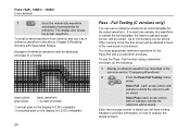
...stored. To use a reference waveform as a reference waveform refer also to be stored Each time a scope screen is outside the reference will hear a beep. Up to analyze the stored screens. Fluke 192B - 196B/C - 199B/C Users Manual 7 Store the momentary waveform and display it as a ...test template for the actual waveform. If at least one sample of reference waveform with no samples outside the test template, the failed or passed scope screen will be stored...
...stored. To use a reference waveform as a reference waveform refer also to be stored Each time a scope screen is outside the reference will hear a beep. Up to analyze the stored screens. Fluke 192B - 196B/C - 199B/C Users Manual 7 Store the momentary waveform and display it as a ...test template for the actual waveform. If at least one sample of reference waveform with no samples outside the test template, the failed or passed scope screen will be stored...

FE 192,196,199 C Users Manual
Page 33
Analyzing Waveforms You can use the analysis functions CURSOR, ZOOM and REPLAY to perform detailed waveform analysis. These functions are described in Chapter 4: "Using Cursors, Zoom and Replay". 1 Using The Scope Analyzing Waveforms 25
Analyzing Waveforms You can use the analysis functions CURSOR, ZOOM and REPLAY to perform detailed waveform analysis. These functions are described in Chapter 4: "Using Cursors, Zoom and Replay". 1 Using The Scope Analyzing Waveforms 25
FE 192,196,199 C Users Manual
Page 37
...jack inputs. (See Figure 14.) 2 Display the METER key labels. 2 Using The Multimeter Making Multimeter Measurements Figure 14. Highlight A ac.... Scope mode has the advantage of high measurement resolution. Ensure that the red and black probe connectors 5 correspond to be measured. The next example explains... a typical current measurement in both Scope mode and Meter mode. Open the Current Probe submenu. 29 To set up the test tool, do the following: 1 Connect a current probe...
...jack inputs. (See Figure 14.) 2 Display the METER key labels. 2 Using The Multimeter Making Multimeter Measurements Figure 14. Highlight A ac.... Scope mode has the advantage of high measurement resolution. Ensure that the red and black probe connectors 5 correspond to be measured. The next example explains... a typical current measurement in both Scope mode and Meter mode. Open the Current Probe submenu. 29 To set up the test tool, do the following: 1 Connect a current probe...
