
User Manual
Page 1
All rights reserved. Specifications are trademarks of their respective companies. All product names are subject to change without notice. 1736/1738 Power Logger Users Manual September 2015 © 2015 Fluke Corporation.
All rights reserved. Specifications are trademarks of their respective companies. All product names are subject to change without notice. 1736/1738 Power Logger Users Manual September 2015 © 2015 Fluke Corporation.

User Manual
Page 9
R-Coil Operation Principle ...8 5. Characteristics of Figures Figure Title Page 1. Replacement Parts ...55 13. Power Supply and Battery ...11 7. Power Logger to PC Connections 57 14. Inrush Characteristics and Relation with Color Coding 9 6. List of a Voltage Interruption 41 11. Adapter Installation ...6 3. Test Leads with Start Menu 42 12. Characteristics of a Voltage Dip 40 10. iFlex Probe Window ...74 vii Country-Specific Mains Power Cable 5 2. Magnet Hanger Kit ...7 4. Decal for Connector Panel ...15 8. Characteristics of a Voltage Swell 40 9.
R-Coil Operation Principle ...8 5. Characteristics of Figures Figure Title Page 1. Replacement Parts ...55 13. Power Supply and Battery ...11 7. Power Logger to PC Connections 57 14. Inrush Characteristics and Relation with Color Coding 9 6. List of a Voltage Interruption 41 11. Adapter Installation ...6 3. Test Leads with Start Menu 42 12. Characteristics of a Voltage Dip 40 10. iFlex Probe Window ...74 vii Country-Specific Mains Power Cable 5 2. Magnet Hanger Kit ...7 4. Decal for Connector Panel ...15 8. Characteristics of a Voltage Swell 40 9.
User Manual
Page 11
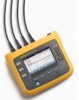
...Harmonics: Harmonic components up to configure, verify, and download measurement sessions without the need of the measurement results. 1 Introduction The 1736 and 1738 Power Loggers (the Logger or Product) is included with the Product for a thorough energy analysis and professional report of a computer at the measurement location. All illustrations... drive support, it is easy to and including the 50th and Total Harmonic Distortion of Voltage and Current Fluke software, Energy Analyze Plus, is a compact device for energy and power quality surveys. With a built-in this manual show the...
...Harmonics: Harmonic components up to configure, verify, and download measurement sessions without the need of the measurement results. 1 Introduction The 1736 and 1738 Power Loggers (the Logger or Product) is included with the Product for a thorough energy analysis and professional report of a computer at the measurement location. All illustrations... drive support, it is easy to and including the 50th and Total Harmonic Distortion of Voltage and Current Fluke software, Energy Analyze Plus, is a compact device for energy and power quality surveys. With a built-in this manual show the...

User Manual
Page 13
... parts with hazardous live voltage such as in damp or wet environments. • Use only the external mains power supply included with sharp objects • Do not use test leads if they are damaged. Power Logger Safety Information • Do not touch voltages >30 V ac rms, 42 V ac peak, or 60 V dc. •...
... parts with hazardous live voltage such as in damp or wet environments. • Use only the external mains power supply included with sharp objects • Do not use test leads if they are damaged. Power Logger Safety Information • Do not touch voltages >30 V ac rms, 42 V ac peak, or 60 V dc. •...
User Manual
Page 15
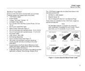
... Probe Safety Information) • 4 GB USB Flash Drive (includes Users Manual and PC application software, Fluke Energy Analyze Plus) Power Logger Before You Start The 1738 Power Logger also includes these items in your purchase. Check www.fluke.com for the 1736 Power Logger as optional accessories. Note The WiFi/BLE adapter is included only when the radio certification...
... Probe Safety Information) • 4 GB USB Flash Drive (includes Users Manual and PC application software, Fluke Energy Analyze Plus) Power Logger Before You Start The 1738 Power Logger also includes these items in your purchase. Check www.fluke.com for the 1736 Power Logger as optional accessories. Note The WiFi/BLE adapter is included only when the radio certification...

User Manual
Page 17
... red and black test leads. Magnet Hanger Kit hcf058.eps 7 On installations where the access to Neutral is used to: • Hang the Logger with the threephase test lead, use the black test lead to extend the Neutral lead. Magnet Hanger Kit The accessory shown in Figure 3 is... reach with power supply attached (use two magnets) • Hang the Logger separately (use two magnets) • Hang the power supply separately (use one magnet) Voltage Test Leads Voltage test leads are four-core, flat, test leads that do not tangle and can be installed in tight spaces. Power Logger Before You ...
... red and black test leads. Magnet Hanger Kit hcf058.eps 7 On installations where the access to Neutral is used to: • Hang the Logger with the threephase test lead, use the black test lead to extend the Neutral lead. Magnet Hanger Kit The accessory shown in Figure 3 is... reach with power supply attached (use two magnets) • Hang the Logger separately (use two magnets) • Hang the power supply separately (use one magnet) Voltage Test Leads Voltage test leads are four-core, flat, test leads that do not tangle and can be installed in tight spaces. Power Logger Before You ...

User Manual
Page 19
... are appropriate for your local wiring codes on the right side of a built-in place. Use the color clips for attaching a lock-and-cable apparatus. Power Logger Before You Start Kensington Lock A Kensington Security Slot (also called a K-Slot or Kensington lock) is available from most electronics and computer suppliers. Apply the clips....eps Figure 5. Test Leads with a key or combination lock attached to secure it in anti-theft system. See Figure 5. This lock is part of the Logger (see item 6 in place with Color Coding 9
... are appropriate for your local wiring codes on the right side of a built-in place. Use the color clips for attaching a lock-and-cable apparatus. Power Logger Before You Start Kensington Lock A Kensington Security Slot (also called a K-Slot or Kensington lock) is available from most electronics and computer suppliers. Apply the clips....eps Figure 5. Test Leads with a key or combination lock attached to secure it in anti-theft system. See Figure 5. This lock is part of the Logger (see item 6 in place with Color Coding 9

User Manual
Page 21
... is preferred in locations where the Logger with the power supply attached is connected with a dc power cable. Storage When not in use, keep the Logger in a cabinet between the door and panel. To use on and turns off the Logger) • recharges the battery Power Logger Storage The power cord/measurement line cover slides to select the...
... is preferred in locations where the Logger with the power supply attached is connected with a dc power cable. Storage When not in use, keep the Logger in a cabinet between the door and panel. To use on and turns off the Logger) • recharges the battery Power Logger Storage The power cord/measurement line cover slides to select the...

User Manual
Page 23
Table 3. Front Panel 3 4 2 5 Item Control Description Power on/off and status Meter, Power, or Logger function selection Memory/Setup selection Cursor control Selection control Kensington lock &#... 1 9 8 6 Touch screen display 7 hcf023.eps 13 See Table 4 for a list of the connectors and their functions. Power Logger Navigation and User Interface Navigation and User Interface See Table 3 for a list of the front panel controls and their functions.
Table 3. Front Panel 3 4 2 5 Item Control Description Power on/off and status Meter, Power, or Logger function selection Memory/Setup selection Cursor control Selection control Kensington lock &#... 1 9 8 6 Touch screen display 7 hcf023.eps 13 See Table 4 for a list of the connectors and their functions. Power Logger Navigation and User Interface Navigation and User Interface See Table 3 for a list of the front panel controls and their functions.

User Manual
Page 25
The decals correspond to the wiring color codes used in Figure 7. USA (4275029) Power Logger Navigation and User Interface Canada (4280546) Europe/UK (New STD 4280531) UK (4280554) China (4280568) Figure 7. Decal for your local wiring codes around the current and voltage inputs on the connector panel as shown in the USA, Europe and UK, UK (old), Canada, and China. Apply the decal appropriate for Connector Panel hcf022.eps 15 Applying the Connector Panel Decal Self-adhesive decals are supplied with the Logger.
The decals correspond to the wiring color codes used in Figure 7. USA (4275029) Power Logger Navigation and User Interface Canada (4280546) Europe/UK (New STD 4280531) UK (4280554) China (4280568) Figure 7. Decal for your local wiring codes around the current and voltage inputs on the connector panel as shown in the USA, Europe and UK, UK (old), Canada, and China. Apply the decal appropriate for Connector Panel hcf022.eps 15 Applying the Connector Panel Decal Self-adhesive decals are supplied with the Logger.

User Manual
Page 27
Power from Battery The Logger can operate on and is ready to the power supply or dc power cord. The Logger turns on battery power without a connection to use in Push .
Power from Battery The Logger can operate on and is ready to the power supply or dc power cord. The Logger turns on battery power without a connection to use in Push .

User Manual
Page 29
... on current channels as a guide for voltage and current. Function Selection Buttons The Logger has three buttons that toggle between voltage and current • understand the consequence of available parameters. Power Logger Function Selection Buttons The scope screen is a bar chart of the display: Meter ...sensor and range • identify the phase sequence of voltage and current • visually inspect the phase shift between the Meter, Power, and Logger function modes. It is included in the upper left corner of the harmonics h02 ... When % of the fundamental, a selectable ...
... on current channels as a guide for voltage and current. Function Selection Buttons The Logger has three buttons that toggle between voltage and current • understand the consequence of available parameters. Power Logger Function Selection Buttons The scope screen is a bar chart of the display: Meter ...sensor and range • identify the phase sequence of voltage and current • visually inspect the phase shift between the Meter, Power, and Logger function modes. It is included in the upper left corner of the harmonics h02 ... When % of the fundamental, a selectable ...

User Manual
Page 31
... compliance evaluation. Set the Harmonics Standard to get pseudo-apparent power readings. Verify the circuit capacity before adding additional load. - Power Logger Function Selection Buttons Power Quality Select the power quality standard (available on 1738 or 1736 with 1736/Upgrade or IEEE 519/Report license) ... required. 21 Study Type Depending on the ratio of maximum demand load current IL to the short circuit current ISC. The Logger supports these values at a later time with and . Identify situations where the allowable load can update these parameters...
... compliance evaluation. Set the Harmonics Standard to get pseudo-apparent power readings. Verify the circuit capacity before adding additional load. - Power Logger Function Selection Buttons Power Quality Select the power quality standard (available on 1738 or 1736 with 1736/Upgrade or IEEE 519/Report license) ... required. 21 Study Type Depending on the ratio of maximum demand load current IL to the short circuit current ISC. The Logger supports these values at a later time with and . Identify situations where the allowable load can update these parameters...

User Manual
Page 33
Energy Study hcf042.eps Energy Study hcf043.eps hcf042-2.eps Load Study (no voltage measurement) hcf044.eps Load Study (no voltage measurement) 23 Power Logger Function Selection Buttons Split Phase Example: A North American residential installation at a branch circuit. Single Phase IT The logger has a galvanic isolation between the voltage inputs and ground based signals like USB and mains input. This would be the connection at the service entrance. Example: Used in Norway and in some hospitals.
Energy Study hcf042.eps Energy Study hcf043.eps hcf042-2.eps Load Study (no voltage measurement) hcf044.eps Load Study (no voltage measurement) 23 Power Logger Function Selection Buttons Split Phase Example: A North American residential installation at a branch circuit. Single Phase IT The logger has a galvanic isolation between the voltage inputs and ground based signals like USB and mains input. This would be the connection at the service entrance. Example: Used in Norway and in some hospitals.

User Manual
Page 35
Energy Study hcf049.eps Energy Study hcf051.eps hcf050.eps Load Study (no voltage measurement) hcf052.eps Load Study (no voltage measurement) 25 As an option, you can be simplified by measuring only one phase and assuming the same voltages/currents on the neutral line. Power Logger Function Selection Buttons 3-Ф Delta Example: Often found in industrial settings where electric motors are used. 3-Ф Wye Balanced Example: For symmetrical loads like motors the connection can measure harmonics with a current probe on the other phases.
Energy Study hcf049.eps Energy Study hcf051.eps hcf050.eps Load Study (no voltage measurement) hcf052.eps Load Study (no voltage measurement) 25 As an option, you can be simplified by measuring only one phase and assuming the same voltages/currents on the neutral line. Power Logger Function Selection Buttons 3-Ф Delta Example: Often found in industrial settings where electric motors are used. 3-Ф Wye Balanced Example: For symmetrical loads like motors the connection can measure harmonics with a current probe on the other phases.

User Manual
Page 37
Energy Study hcf061.eps Energy Study hcf063.eps hcf062.eps Load Study (no voltage measurement) hcf064.eps Load Study (no voltage measurement) 27 3-Ф High Leg Delta Example: This topology is used to provide an additional voltage that is simplified with only one phase measurement and assuming the same voltages/currents on the other phases. Power Logger Function Selection Buttons 3-Ф Delta Balanced Example: For symmetrical loads like motors, the connection is half the phase to phase voltage.
Energy Study hcf061.eps Energy Study hcf063.eps hcf062.eps Load Study (no voltage measurement) hcf064.eps Load Study (no voltage measurement) 27 3-Ф High Leg Delta Example: This topology is used to provide an additional voltage that is simplified with only one phase measurement and assuming the same voltages/currents on the other phases. Power Logger Function Selection Buttons 3-Ф Delta Balanced Example: For symmetrical loads like motors, the connection is half the phase to phase voltage.

User Manual
Page 39
... offset in the sensor configuration dialog and is required. Resistor values >500 Ω are automatically calculated with the measurement range of the five custom sensors. 2. Power Logger Function Selection Buttons • Use up to 8 characters to configure the measurement Unit of 50 Ω is recommended. For all other . Sensor Type: Select 0-10...
... offset in the sensor configuration dialog and is required. Resistor values >500 Ω are automatically calculated with the measurement range of the five custom sensors. 2. Power Logger Function Selection Buttons • Use up to 8 characters to configure the measurement Unit of 50 Ω is recommended. For all other . Sensor Type: Select 0-10...

User Manual
Page 41
... verify the suggested modifications carefully before you to detect a better phase map or when no errors are detected. Power Logger Function Selection Buttons Power - Push (Correct Digitally) to toggle between full bandwidth power values and power of a manual correction. 3. This screen allows you apply the digital correction. The algorithm works in var •...
... verify the suggested modifications carefully before you to detect a better phase map or when no errors are detected. Power Logger Function Selection Buttons Power - Push (Correct Digitally) to toggle between full bandwidth power values and power of a manual correction. 3. This screen allows you apply the digital correction. The algorithm works in var •...

User Manual
Page 43
...You can configure a scheduled recording. Also, you must push the Start Logging button. 33 incremental file number The counter resets when the Logger is either configured by the duration and the start date and time or by the start date and time and stop the logging session.... Note Even when a start recording. 4. To select between Load Study and Energy Study: 1. Name The Logger auto-generates a file name with up the Logger to factory defaults. Power Logger Function Selection Buttons Duration and Recording Start/Stop Date and Time You can manually stop date and time. You ...
...You can configure a scheduled recording. Also, you must push the Start Logging button. 33 incremental file number The counter resets when the Logger is either configured by the duration and the start date and time or by the start date and time and stop the logging session.... Note Even when a start recording. 4. To select between Load Study and Energy Study: 1. Name The Logger auto-generates a file name with up the Logger to factory defaults. Power Logger Function Selection Buttons Duration and Recording Start/Stop Date and Time You can manually stop date and time. You ...

User Manual
Page 45
... demand interval and can select one of the available overview screens: • Power Screen provides access to V, A, Hz, + (A, Hz, + for load studies), power, and energy • PQ Health (available on 1738 or 1736 with 1736/Upgrade or IEEE 519/Report license) Screen provides access to... to Power Quality graphs, harmonics, and events Power/Load Study Overview The screen shows the overview chart with each new average calculation interval at a maximum of an active recording. Energy costs Enter the costs/kWh for demand energy. Power Logger Function Selection Buttons The Logger home ...
... demand interval and can select one of the available overview screens: • Power Screen provides access to V, A, Hz, + (A, Hz, + for load studies), power, and energy • PQ Health (available on 1738 or 1736 with 1736/Upgrade or IEEE 519/Report license) Screen provides access to... to Power Quality graphs, harmonics, and events Power/Load Study Overview The screen shows the overview chart with each new average calculation interval at a maximum of an active recording. Energy costs Enter the costs/kWh for demand energy. Power Logger Function Selection Buttons The Logger home ...


