
Fluke 1735 Three Phase Power Logger Datasheet
Page 1
..., harmonics and captures voltage events. • Record power and associated param- Fluke 1735 Three-Phase Power Logger Technical Data Electrical load studies, energy consumption testing, and general power quality logging The Fluke 1735 Three-Phase Power Logger is the ideal electrician or technician's tool for up the 1735 in seconds, with the included flexible current probes and color display. ments with energy consumption...
..., harmonics and captures voltage events. • Record power and associated param- Fluke 1735 Three-Phase Power Logger Technical Data Electrical load studies, energy consumption testing, and general power quality logging The Fluke 1735 Three-Phase Power Logger is the ideal electrician or technician's tool for up the 1735 in seconds, with the included flexible current probes and color display. ments with energy consumption...

Fluke 1735 Three Phase Power Logger Datasheet
Page 2
... hard-to 45 days and view saved data on-screen or on a computer. Capture voltage events using user-defined thresholds. Easily customize the report. 2 Fluke Corporation 1735 Three-Phase Power Logger Create professional reports. verify electrical system capacity before , and after improvements, to the 50th. With memory for high accuracy in simple graphs and tables...
... hard-to 45 days and view saved data on-screen or on a computer. Capture voltage events using user-defined thresholds. Easily customize the report. 2 Fluke Corporation 1735 Three-Phase Power Logger Create professional reports. verify electrical system capacity before , and after improvements, to the 50th. With memory for high accuracy in simple graphs and tables...

Fluke 1735 Three Phase Power Logger Datasheet
Page 3
...coefficient Intrinsic error Operating error Climatic class Housing ± 0.1 % of m. deviation is guaranteed for two years. v. + 10 digit) 0.1 V 3 Fluke Corporation 1735 Three-Phase Power Logger deviation is guaranteed for two years C1 (IEC 654-1) -5 °C to +45 °C (+41 °F to +113 °F), 5 % to... working temperature range, use the temperature coefficient below. Specifications General Display Quality Memory Interface Sample rate Line frequency Power supply Operation time with battery Dimensions Weight ¼ VGA Graphic Color transmissive displays 320 x 240 Pixel with...
...coefficient Intrinsic error Operating error Climatic class Housing ± 0.1 % of m. deviation is guaranteed for two years. v. + 10 digit) 0.1 V 3 Fluke Corporation 1735 Three-Phase Power Logger deviation is guaranteed for two years C1 (IEC 654-1) -5 °C to +45 °C (+41 °F to +113 °F), 5 % to... working temperature range, use the temperature coefficient below. Specifications General Display Quality Memory Interface Sample rate Line frequency Power supply Operation time with battery Dimensions Weight ¼ VGA Graphic Color transmissive displays 320 x 240 Pixel with...

Fluke 1735 Three Phase Power Logger Datasheet
Page 4
... digit) ± (3 % of full scale v Typical range with voltage range 830 V delta- Reactive, D - v. + 10 digit) 15 A Intrinsic error: ± (0.5 % of m.v.+ 10 digit) 0.01 Hz 4 Fluke Corporation 1735 Three-Phase Power Logger Frequency measurement Measuring range Intrinsic error Operating error Resolution 46 Hz to 54 Hz and 56 Hz to 64 Hz ± (0.2 % of m.v. + 5 digit) ±...
... digit) ± (3 % of full scale v Typical range with voltage range 830 V delta- Reactive, D - v. + 10 digit) 15 A Intrinsic error: ± (0.5 % of m.v.+ 10 digit) 0.01 Hz 4 Fluke Corporation 1735 Three-Phase Power Logger Frequency measurement Measuring range Intrinsic error Operating error Resolution 46 Hz to 54 Hz and 56 Hz to 64 Hz ± (0.2 % of m.v. + 5 digit) ±...

Fluke 1735 Three Phase Power Logger Datasheet
Page 5
... (5 A/50 A) for THD r 10 % ± 5 % at Inom Vnom: Nominal voltage range. Printed in U.S.A. 5/2006 2634932 D-EN-N Rev A Keeping your world up and running.™ 5 Fluke Corporation 1735 Three-Phase Power Logger Fluke Corporation PO Box 9090, Everett, WA USA 98206 Fluke Europe B.V. All rights reserved. Events Detection of voltage dips, voltage swells and voltage interruptions with rollers...
... (5 A/50 A) for THD r 10 % ± 5 % at Inom Vnom: Nominal voltage range. Printed in U.S.A. 5/2006 2634932 D-EN-N Rev A Keeping your world up and running.™ 5 Fluke Corporation 1735 Three-Phase Power Logger Fluke Corporation PO Box 9090, Everett, WA USA 98206 Fluke Europe B.V. All rights reserved. Events Detection of voltage dips, voltage swells and voltage interruptions with rollers...

User Manual
Page 4
...Power 23 Events 24 Connecting the Power Logger to the Network 24 Color Coding Wire Clips 25 Single and Split Phase Connections 26 Split Phase 28 Measurement in a Three-Phase Power Network 29 Volts / Amps / Hertz 32 Logging 33 Measurement 33 Save 34 Logging Function 34 Power 35 Measurement 36 Three-Phase Power... Measurement 45 Save 46 Power Log PC Software 46 Installing Power Log Software 46 Starting Power Log 46 Using Power Log 47 Energy Recording with Fluke Power Log 49 Recording Power (Demand) with 1735 Power Logger 51 Inside the Logger 52 Line Power or Battery Mode 52 ...
...Power 23 Events 24 Connecting the Power Logger to the Network 24 Color Coding Wire Clips 25 Single and Split Phase Connections 26 Split Phase 28 Measurement in a Three-Phase Power Network 29 Volts / Amps / Hertz 32 Logging 33 Measurement 33 Save 34 Logging Function 34 Power 35 Measurement 36 Three-Phase Power... Measurement 45 Save 46 Power Log PC Software 46 Installing Power Log Software 46 Starting Power Log 46 Using Power Log 47 Energy Recording with Fluke Power Log 49 Recording Power (Demand) with 1735 Power Logger 51 Inside the Logger 52 Line Power or Battery Mode 52 ...

User Manual
Page 9
...; Connections-Blondel (Aron, Three-Element Delta) ...32 11. Split Phase Connections 29 8. Three-Phase Wye Connections 30 9. Fluke Power Log Displaying Three Phases of Figures Figure Title Page 1. Power Logger Connectors 11 4. List of Voltage and Current 48 13. Display Symbols 8 2. Using the Optional Mini Clamps 25 6. Three-Phase Delta Δ Connections-Blondel (Aron, Two-Element Delta) ...31...
...; Connections-Blondel (Aron, Three-Element Delta) ...32 11. Split Phase Connections 29 8. Three-Phase Wye Connections 30 9. Fluke Power Log Displaying Three Phases of Figures Figure Title Page 1. Power Logger Connectors 11 4. List of Voltage and Current 48 13. Display Symbols 8 2. Using the Optional Mini Clamps 25 6. Three-Phase Delta Δ Connections-Blondel (Aron, Two-Element Delta) ...31...

User Manual
Page 15
... A Male Model or Part Number Fluke-1735 2584895 2441372 2637462 3276205 2540726 2637481 2625171 1642656 2583487 3611908 3671726 5 Table 2. Standard Equipment Equipment Power Logger Battery Charger, BC1735, 115V/230V 50/60 Hz International AC Power Plug Set For Battery Charger FS17XX, Shielded 4-Phase Flexi Set for the Power Logger is listed in Table 3. Power Logger Standard and Optional Accessories Standard...
... A Male Model or Part Number Fluke-1735 2584895 2441372 2637462 3276205 2540726 2637481 2625171 1642656 2583487 3611908 3671726 5 Table 2. Standard Equipment Equipment Power Logger Battery Charger, BC1735, 115V/230V 50/60 Hz International AC Power Plug Set For Battery Charger FS17XX, Shielded 4-Phase Flexi Set for the Power Logger is listed in Table 3. Power Logger Standard and Optional Accessories Standard...

User Manual
Page 29
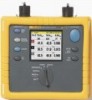
... a current transformer is being measured, it is automatically recognized, but only at power-up. edx013.bmp 19 Power Logger Basic Operation Instrument Setup In this menu option you can make adjustments in the submenu for: • Current Probes • Voltage Transformers • Phase Identification • Backlight • Version and Calibration These are described individually...
... a current transformer is being measured, it is automatically recognized, but only at power-up. edx013.bmp 19 Power Logger Basic Operation Instrument Setup In this menu option you can make adjustments in the submenu for: • Current Probes • Voltage Transformers • Phase Identification • Backlight • Version and Calibration These are described individually...
User Manual
Page 31
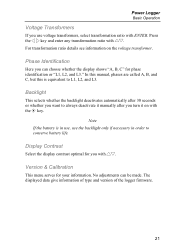
... for you with ENTER. Display Contrast Select the display contrast optimal for your information. Power Logger Basic Operation Voltage Transformers If you use the backlight only if necessary in use, use voltage transformers, select transformation ratio with 21. Phase Identification Here you can be made. Backlight This selects whether the backlight deactivates automatically...
... for you with ENTER. Display Contrast Select the display contrast optimal for your information. Power Logger Basic Operation Voltage Transformers If you use the backlight only if necessary in use, use voltage transformers, select transformation ratio with 21. Phase Identification Here you can be made. Backlight This selects whether the backlight deactivates automatically...

User Manual
Page 33
... power, apparent power, distortion power and the appropriate power factor. The contribution of each rotary switch position. Power This function indicates the values of different frequency and amplitude. Scope Scope shows the voltages, currents and the ϕ (phase) angle in the other functions. With this... the voltage and current values at the cursor position. Measuring Functions Power Logger Measuring Functions Overview The following information provides an overview of each of these individual sine waves is the power network quality. At the same time you analyze the signal in...
... power, apparent power, distortion power and the appropriate power factor. The contribution of each rotary switch position. Power This function indicates the values of different frequency and amplitude. Scope Scope shows the voltages, currents and the ϕ (phase) angle in the other functions. With this... the voltage and current values at the cursor position. Measuring Functions Power Logger Measuring Functions Overview The following information provides an overview of each of these individual sine waves is the power network quality. At the same time you analyze the signal in...

User Manual
Page 35
Using the Optional Mini Clamps edx045f.eps Color Coding Wire Clips Your Logger includes a set of which current probe lead and voltage lead belongs to which phase. Use the plastic rod tool to the test leads. These help you can attach to help you keep track of color clips that you attach the clips. 25 The large clips are for the current probe leads and the small clips are for the voltage leads. Single Insulated Current Carrying Conductor Release Button Power Logger Measuring Functions Load Direction Arrow AC C6U00RVRECNASTTiE5RICIsIIALLANMUMPBER Tactile Barrier Figure 5.
Using the Optional Mini Clamps edx045f.eps Color Coding Wire Clips Your Logger includes a set of which current probe lead and voltage lead belongs to which phase. Use the plastic rod tool to the test leads. These help you can attach to help you keep track of color clips that you attach the clips. 25 The large clips are for the current probe leads and the small clips are for the voltage leads. Single Insulated Current Carrying Conductor Release Button Power Logger Measuring Functions Load Direction Arrow AC C6U00RVRECNASTTiE5RICIsIIALLANMUMPBER Tactile Barrier Figure 5.

User Manual
Page 37
Power Logger Measuring Functions L1 L N L1 L2 L3 N N L2 L3 1735 POWER LOGGER CURRENT INPUT MAX 30V HORLUDN REMCEOARSDURE CURSOR 600V CAT VOLTAGE INPUT ENSTSCEARRVEEEN EMSECNU EVENTS POWER HARMSOCNOIPCES MEVTAERHOz FF Figure 6. Single Phase Connections edx040.eps 27
Power Logger Measuring Functions L1 L N L1 L2 L3 N N L2 L3 1735 POWER LOGGER CURRENT INPUT MAX 30V HORLUDN REMCEOARSDURE CURSOR 600V CAT VOLTAGE INPUT ENSTSCEARRVEEEN EMSECNU EVENTS POWER HARMSOCNOIPCES MEVTAERHOz FF Figure 6. Single Phase Connections edx040.eps 27

User Manual
Page 39
Split Phase Connections edx041.eps Measurement in a Three-Phase Power Network In order to measure all phases in the three-phase power network with the Logger you attach your Logger to the measuring power network according to the following figures. L1 L1 L2 N Power Logger Measuring Functions L2 N L1 L2 L3 N L3 1735 POWER LOGGER CURRENT INPUT MAX 30V HORLUDN REMCEOARSDURE CURSOR 600V CAT VOLTAGE INPUT ENSTSCEARRVEEEN EMSECNU POWER EVENTS HARMSOCMNOEVIPCTESAERHOz FF Figure 7. See 'Power' for further details. 29
Split Phase Connections edx041.eps Measurement in a Three-Phase Power Network In order to measure all phases in the three-phase power network with the Logger you attach your Logger to the measuring power network according to the following figures. L1 L1 L2 N Power Logger Measuring Functions L2 N L1 L2 L3 N L3 1735 POWER LOGGER CURRENT INPUT MAX 30V HORLUDN REMCEOARSDURE CURSOR 600V CAT VOLTAGE INPUT ENSTSCEARRVEEEN EMSECNU POWER EVENTS HARMSOCMNOEVIPCTESAERHOz FF Figure 7. See 'Power' for further details. 29

User Manual
Page 40
Three-Phase Wye Connections edx042.eps 30 1735 Users Manual Voltage: A (L1) Mains Line B (L2) C (L3) N Current: A (L1) B (L2) C (L3) N Mains Line A (L1) B (L2) C (L3) N Test Leads A (L1) B (L2) C (L3) N Test Leads L1 L2 L3 N L1 L2 L3 N L1 L2 L3 N 1735 POWER LOGGER CURRENT INPUT MAX 30V HORLUDN REMCEOARSDURE CURSOR 600V CAT VOLTAGE INPUT ENSTSCEARRVEEEN EMSECNU EVENTS POWER HARMSOCNOIPCES MEVTAERHOz FF Figure 8.
Three-Phase Wye Connections edx042.eps 30 1735 Users Manual Voltage: A (L1) Mains Line B (L2) C (L3) N Current: A (L1) B (L2) C (L3) N Mains Line A (L1) B (L2) C (L3) N Test Leads A (L1) B (L2) C (L3) N Test Leads L1 L2 L3 N L1 L2 L3 N L1 L2 L3 N 1735 POWER LOGGER CURRENT INPUT MAX 30V HORLUDN REMCEOARSDURE CURSOR 600V CAT VOLTAGE INPUT ENSTSCEARRVEEEN EMSECNU EVENTS POWER HARMSOCNOIPCES MEVTAERHOz FF Figure 8.

User Manual
Page 41
L1 L1 L2 L3 Power Logger Measuring Functions L1 L2 L3 N L3 L2 N 1735 POWER LOGGER CURRENT INPUT MAX 30V HORLUDN REMCEOARSDURE CURSOR 600V CAT VOLTAGE INPUT ENSTSCEARRVEEEN EMSECNU POWER EVENTS HARMSOCMNOEVIPCTESAERHOz FF edx043.eps Figure 9. Three-Phase Delta Δ Connections-Blondel (Aron, Two-Element Delta) 31
L1 L1 L2 L3 Power Logger Measuring Functions L1 L2 L3 N L3 L2 N 1735 POWER LOGGER CURRENT INPUT MAX 30V HORLUDN REMCEOARSDURE CURSOR 600V CAT VOLTAGE INPUT ENSTSCEARRVEEEN EMSECNU POWER EVENTS HARMSOCMNOEVIPCTESAERHOz FF edx043.eps Figure 9. Three-Phase Delta Δ Connections-Blondel (Aron, Two-Element Delta) 31
User Manual
Page 42
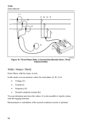
In this mode you can measure values for each phase (A, B, C) of the neutral-conductor current is also possible to log the values with the rotary switch. It is optional. 32 Measurement or calculation of • ...-conductor current (In) You can determine and store the values. Three-Phase Delta Δ Connections-Blondel (Aron, ThreeElement Delta) Volts / Amps / Hertz Select Meter with the logging function. 1735 Users Manual L1 L1 L2 L3 L2 L3 L1 L2 L3 N N 1735 POWER LOGGER CURRENT INPUT MAX 30V HORLUDN REMCEOARSDURE CURSOR 600V CAT VOLTAGE INPUT ENSTSCEARRVEEEN...
In this mode you can measure values for each phase (A, B, C) of the neutral-conductor current is also possible to log the values with the rotary switch. It is optional. 32 Measurement or calculation of • ...-conductor current (In) You can determine and store the values. Three-Phase Delta Δ Connections-Blondel (Aron, ThreeElement Delta) Volts / Amps / Hertz Select Meter with the logging function. 1735 Users Manual L1 L1 L2 L3 L2 L3 L1 L2 L3 N N 1735 POWER LOGGER CURRENT INPUT MAX 30V HORLUDN REMCEOARSDURE CURSOR 600V CAT VOLTAGE INPUT ENSTSCEARRVEEEN...

User Manual
Page 43
maximum of values - minimum of values and 4 5 - Power Logger Measuring Functions Logging In Logging mode, the following values are recorded for every phase (A, B, C) • Voltage (V) and • Current (I) and the value of the • Frequency (F) These values can be recorded in the instrument, downloaded and evaluated with the Fluke Power Log software package Measurement If you...
maximum of values - minimum of values and 4 5 - Power Logger Measuring Functions Logging In Logging mode, the following values are recorded for every phase (A, B, C) • Voltage (V) and • Current (I) and the value of the • Frequency (F) These values can be recorded in the instrument, downloaded and evaluated with the Fluke Power Log software package Measurement If you...

User Manual
Page 45
V and F - Power Select Power with Fluke Power Log software package. Power Logger Measuring Functions 21 Select between the individual phases 4 5 Select between the two representation modes: - V and In Analyzing the measured values of the recorder function: edx025.bmp These values can get the following values for each phase (A, B, C): • Power (P) in W (for each phase and its sum Ptot). • Reactive power (Q) in...
V and F - Power Select Power with Fluke Power Log software package. Power Logger Measuring Functions 21 Select between the individual phases 4 5 Select between the two representation modes: - V and In Analyzing the measured values of the recorder function: edx025.bmp These values can get the following values for each phase (A, B, C): • Power (P) in W (for each phase and its sum Ptot). • Reactive power (Q) in...

User Manual
Page 47
...started again. With Hold/Run the values displayed at the moment "freeze" and the measurement is indicated at the top of the measurement display. Power Logger Measuring Functions - kW, kVA and kWh - A further press of 21 gives a detail view of A or B or C, the active ...representation of the individual phase values. Capacitor or inductance symbols issue information about capacitive or inductive reactive power. kW, kVA and kVARh On pressing 21 the accumulated energy function becomes active, this must be selected. Three-Phase Power Theory By switching the Power Network setting from wye...
...started again. With Hold/Run the values displayed at the moment "freeze" and the measurement is indicated at the top of the measurement display. Power Logger Measuring Functions - kW, kVA and kWh - A further press of 21 gives a detail view of A or B or C, the active ...representation of the individual phase values. Capacitor or inductance symbols issue information about capacitive or inductive reactive power. kW, kVA and kVARh On pressing 21 the accumulated energy function becomes active, this must be selected. Three-Phase Power Theory By switching the Power Network setting from wye...


