Fluke 1623 and 1625 Geo Earth Ground Testers Datasheet
Page 2
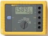
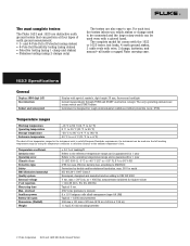
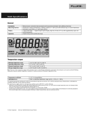
... measurements 250 mm x 133 mm x 187 mm (9.75 in x 5.25 in x 7.35 in) 1.1 kg (2.43 lb) including batteries 2 Fluke Corporation 1623 and 1625 GEO Earth Ground Testers and 4-Pole Fall of Potential (using stakes) • 4-Pole Soil Resistivity testing (using stakes) • Selective testing (using 1 clamp and stakes... (Emission Immunity) Quality system External voltage V ext rejection Measuring time Max. The most complete testers The Fluke 1623 and 1625 are distinctive earth ground testers that can be used over the full working temperature range by double and/or reinforced insulation.
... measurements 250 mm x 133 mm x 187 mm (9.75 in x 5.25 in x 7.35 in) 1.1 kg (2.43 lb) including batteries 2 Fluke Corporation 1623 and 1625 GEO Earth Ground Testers and 4-Pole Fall of Potential (using stakes) • 4-Pole Soil Resistivity testing (using stakes) • Selective testing (using 1 clamp and stakes... (Emission Immunity) Quality system External voltage V ext rejection Measuring time Max. The most complete testers The Fluke 1623 and 1625 are distinctive earth ground testers that can be used over the full working temperature range by double and/or reinforced insulation.
Fluke 1623 and 1625 Geo Earth Ground Testers Datasheet
Page 3
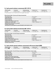
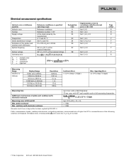
...Max. 100 k7 Max. 100 k7 Measurement is not performed if the current through the current clamp is too low 3 Fluke Corporation 1623 and 1625 GEO Earth Ground Testers RA 3-pole ground resistance measurement (IEC 1557-5) Switch position Resolution Measuring range RA 3-pole 0.001 7 to 10 7 0.001 7 to 19...8226; • •RS[k7]/RA[7 0.2 % Measurement is not performed if the current through the current clamp is too low RA 4-pole ground resistance measurement (IEC 1557-5) Switch position RA 4-pole Resolution 0.001 7 to 10 7 Measuring range 0.001 7 to 19.99 k7 Measuring principle...
...Max. 100 k7 Max. 100 k7 Measurement is not performed if the current through the current clamp is too low 3 Fluke Corporation 1623 and 1625 GEO Earth Ground Testers RA 3-pole ground resistance measurement (IEC 1557-5) Switch position Resolution Measuring range RA 3-pole 0.001 7 to 10 7 0.001 7 to 19...8226; • •RS[k7]/RA[7 0.2 % Measurement is not performed if the current through the current clamp is too low RA 4-pole ground resistance measurement (IEC 1557-5) Switch position RA 4-pole Resolution 0.001 7 to 10 7 Measuring range 0.001 7 to 19.99 k7 Measuring principle...
Fluke 1623 and 1625 Geo Earth Ground Testers Datasheet
Page 4
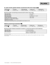
... ± (10 % rdg + 5 d) Measuring principle: Stakeless measurement of resistance in conjunction with the recommended current clamps at the minimum distance specified. 4 Fluke Corporation 1623 and 1625 GEO Earth Ground Testers RA 4-pole selective ground resistance measurement with current clamp (RA Switch position RA 4-pole Resolution 0.001 7 to 10 7 Measuring range 0.001 7 to 19.99 k7 Intrinsic...
... ± (10 % rdg + 5 d) Measuring principle: Stakeless measurement of resistance in conjunction with the recommended current clamps at the minimum distance specified. 4 Fluke Corporation 1623 and 1625 GEO Earth Ground Testers RA 4-pole selective ground resistance measurement with current clamp (RA Switch position RA 4-pole Resolution 0.001 7 to 10 7 Measuring range 0.001 7 to 19.99 k7 Intrinsic...
Fluke 1623 and 1625 Geo Earth Ground Testers Datasheet
Page 5
...transformer, resistance 2-pole with dc voltage respectively across the terminals E (ES) and S. the instrument can be 3 V; • resistance of the auxiliary earth electrode and of the probes: 0 to 100 x RA but b 50 k7; • system voltages between 85 % and 110 % of the nominal...(0.71 in) with a mains supply and/or measuring equipment deriving its output voltage directly from the distribution system. 5 Fluke Corporation 1623 and 1625 GEO Earth Ground Testers The rms value of the series interference voltage shall be used over the full Working temperature range by using the temperature...
...transformer, resistance 2-pole with dc voltage respectively across the terminals E (ES) and S. the instrument can be 3 V; • resistance of the auxiliary earth electrode and of the probes: 0 to 100 x RA but b 50 k7; • system voltages between 85 % and 110 % of the nominal...(0.71 in) with a mains supply and/or measuring equipment deriving its output voltage directly from the distribution system. 5 Fluke Corporation 1623 and 1625 GEO Earth Ground Testers The rms value of the series interference voltage shall be used over the full Working temperature range by using the temperature...

Fluke 1623 and 1625 Geo Earth Ground Testers Datasheet
Page 6
...75 in x 5.25 in x 7.35 in function R* 120 dB (162/3, 50 , 60, 400 Hz) Urms = 250 V 6 Fluke Corporation 1623 and 1625 GEO Earth Ground Testers Urms = 250 V (pertains to misuse) IEC 61326-1:1997 Class A Developed, designed and manufactured to comply with DIN ISO 9001 Complies with probe... (5 % of rdg + 5 digit) Measuring sequence Internal resistance Max. Limits of error Climate class Type of rdg + 2 digit) Earthing resistance (RE) Measuring method Open circuit voltage Short circuit current Measuring frequency Noise rejection Max. accessories and batteries in any combination, max....
...75 in x 5.25 in x 7.35 in function R* 120 dB (162/3, 50 , 60, 400 Hz) Urms = 250 V 6 Fluke Corporation 1623 and 1625 GEO Earth Ground Testers Urms = 250 V (pertains to misuse) IEC 61326-1:1997 Class A Developed, designed and manufactured to comply with DIN ISO 9001 Complies with probe... (5 % of rdg + 5 digit) Measuring sequence Internal resistance Max. Limits of error Climate class Type of rdg + 2 digit) Earthing resistance (RE) Measuring method Open circuit voltage Short circuit current Measuring frequency Noise rejection Max. accessories and batteries in any combination, max....
Fluke 1623 and 1625 Geo Earth Ground Testers Datasheet
Page 7
... sec. Operating Error ± ( 5 % of rdg + 5 digit ) Measuring time Additional error because of probe-, auxiliary earth electrode- probe resistance Max. and a notice that RS or RH are too high. 7 Fluke Corporation 1623 and 1625 GEO Earth Ground Testers max. auxiliary earth electrode resistance typ. 10 % of RE + RS + RH b 1 M7 b 1 M7 Automatic check if error is assumed...
... sec. Operating Error ± ( 5 % of rdg + 5 digit ) Measuring time Additional error because of probe-, auxiliary earth electrode- probe resistance Max. and a notice that RS or RH are too high. 7 Fluke Corporation 1623 and 1625 GEO Earth Ground Testers max. auxiliary earth electrode resistance typ. 10 % of RE + RS + RH b 1 M7 b 1 M7 Automatic check if error is assumed...

Fluke 1623 and 1625 Geo Earth Ground Testers Datasheet
Page 8
... < 600 k7 < 250 k7 17 Selective measurement of all measuring frequencies 0.5 mA With transformer (1000:1) 0.1 mA With transformer (200:1) 3A With a transformer (1000:1) 8 Fluke Corporation 1623 and 1625 GEO Earth Ground Testers Additonal error because of RETOTAL + RS + RH Typ. 8 sec. Urms = 250 V (measurement will not be started) Measuring Range 0.020 7 to 30 k7 Display...
... < 600 k7 < 250 k7 17 Selective measurement of all measuring frequencies 0.5 mA With transformer (1000:1) 0.1 mA With transformer (200:1) 3A With a transformer (1000:1) 8 Fluke Corporation 1623 and 1625 GEO Earth Ground Testers Additonal error because of RETOTAL + RS + RH Typ. 8 sec. Urms = 250 V (measurement will not be started) Measuring Range 0.020 7 to 30 k7 Display...

Fluke 1623 and 1625 Geo Earth Ground Testers Datasheet
Page 9
... , R~ , and R * Value of setpoint entry RK = 0.000 7, variable from 0.000 to 2999 7 Resolution 0.001 7 0.01 7 0.1 7 17 Intrinsic error ± (2 % of measuring adjustment. 2-pole 9 Fluke Corporation 1623 and 1625 GEO Earth Ground Testers interference voltage Max overload typ. 6 sec. 24 V, with higher voltages measurement will not be extended without additional error. reversal of polarity (2-pole or...
... , R~ , and R * Value of setpoint entry RK = 0.000 7, variable from 0.000 to 2999 7 Resolution 0.001 7 0.01 7 0.1 7 17 Intrinsic error ± (2 % of measuring adjustment. 2-pole 9 Fluke Corporation 1623 and 1625 GEO Earth Ground Testers interference voltage Max overload typ. 6 sec. 24 V, with higher voltages measurement will not be extended without additional error. reversal of polarity (2-pole or...
FE 1623 Users Manual
Page 1
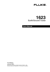
® 1623 Earth/Ground Tester Users Manual PN 2560327 January 2006 © 2006 Fluke Corporation, All rights reserved. Printed in USA All product names are trademarks of their respective companies.
® 1623 Earth/Ground Tester Users Manual PN 2560327 January 2006 © 2006 Fluke Corporation, All rights reserved. Printed in USA All product names are trademarks of their respective companies.

FE 1623 Users Manual
Page 9
... compliance with the safety precautions and regulations set forth below. Disregarding warning notices may lead to be installed and operated by the attached CE-sign. Earth/Ground Tester Introduction This instrument has been manufactured complying with all legal and safety regulations pertaining to each specific application. Unpacking Check delivery for later transport and...
... compliance with the safety precautions and regulations set forth below. Disregarding warning notices may lead to be installed and operated by the attached CE-sign. Earth/Ground Tester Introduction This instrument has been manufactured complying with all legal and safety regulations pertaining to each specific application. Unpacking Check delivery for later transport and...
FE 1623 Users Manual
Page 11
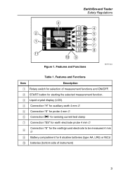
... test clamp G Connection "ES" for earth electrode probe 4 mm ∅ H Connection "E" for the earth/ground electrode to be measured 4 mm ∅ I Battery compartment for 6 alcaline batteries (type AA, LR6) or NiCd J batteries (bottom side of measurement functions and ON/OFF. Earth/Ground Tester Safety Regulations 2 1 11 3 FLUKE 1623 max 50 V P2 S 4 5 6 P1 ES 7 plus FLUKE 8 10 9 Figure 1. Features and...
... test clamp G Connection "ES" for earth electrode probe 4 mm ∅ H Connection "E" for the earth/ground electrode to be measured 4 mm ∅ I Battery compartment for 6 alcaline batteries (type AA, LR6) or NiCd J batteries (bottom side of measurement functions and ON/OFF. Earth/Ground Tester Safety Regulations 2 1 11 3 FLUKE 1623 max 50 V P2 S 4 5 6 P1 ES 7 plus FLUKE 8 10 9 Figure 1. Features and...
FE 1623 Users Manual
Page 12
type (LR6) batteries • 2 measuring leads 1,5 m • 1 connector cable (for RA 2-pole measurements) • 2 alligator clips • 1 Users Manual Carrying Case The part number for the carrying case for the 1623 Earth/Ground Tester and accessories such as the current probes is 2583565. 4 Fluke 1623 Users Manual Accessories The following standard accessories were shipped with your Tester: • 6 alkaline AA -
type (LR6) batteries • 2 measuring leads 1,5 m • 1 connector cable (for RA 2-pole measurements) • 2 alligator clips • 1 Users Manual Carrying Case The part number for the carrying case for the 1623 Earth/Ground Tester and accessories such as the current probes is 2583565. 4 Fluke 1623 Users Manual Accessories The following standard accessories were shipped with your Tester: • 6 alkaline AA -
FE 1623 Users Manual
Page 13
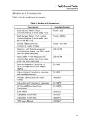
Fully Loaded (Includes manual, 2 leads and 2 clips, ES162P4, EI-1623) Service Replacement Kit (Includes 2 Leads, 2 Clips) Stake Set for 3 Pole Measurement (Includes three stakes, one 25 m cable reel, one 50 m cable reel)... w/25m Wire Cable Reel w/50m Wire 1623 Users Manual Item/Part Number Fluke-1623 Fluke-1623 Kit Fluke-162x-7001 ES-162P3 ES-162P4 EI-1623 EI-162X 2630254 EI-162AC EI-162BN 2630222 2630231 2630246 2560327 5 Basic (Includes manual, 2 leads and 2 clips) Earth Ground Tester - Models and Accessories Description Earth Ground Tester - Models and Accessories Table 2 lists ...
Fully Loaded (Includes manual, 2 leads and 2 clips, ES162P4, EI-1623) Service Replacement Kit (Includes 2 Leads, 2 Clips) Stake Set for 3 Pole Measurement (Includes three stakes, one 25 m cable reel, one 50 m cable reel)... w/25m Wire Cable Reel w/50m Wire 1623 Users Manual Item/Part Number Fluke-1623 Fluke-1623 Kit Fluke-162x-7001 ES-162P3 ES-162P4 EI-1623 EI-162X 2630254 EI-162AC EI-162BN 2630222 2630231 2630246 2560327 5 Basic (Includes manual, 2 leads and 2 clips) Earth Ground Tester - Models and Accessories Description Earth Ground Tester - Models and Accessories Table 2 lists ...

FE 1623 Users Manual
Page 15
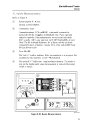
...) should be measured with the supplied connector cable. Connect the stakes with minimum distance between them of 20 m. Operating Instructions Earth/Ground Tester Setup RA 2-pole, 3-pole Measurements To make 2-pole or dead-earth measurements, connect a jumper between terminals H/C2 and S/P2 with the supplied test lead and clip (1.5 m). Refer to be at least...
...) should be measured with the supplied connector cable. Connect the stakes with minimum distance between them of 20 m. Operating Instructions Earth/Ground Tester Setup RA 2-pole, 3-pole Measurements To make 2-pole or dead-earth measurements, connect a jumper between terminals H/C2 and S/P2 with the supplied test lead and clip (1.5 m). Refer to be at least...
FE 1623 Users Manual
Page 17
... until a new measurement is started or the rotary switch is in earth/dirt. A Select function RA 4-pole. Place 2 ground stakes in progress. The "active" symbol indicates that a measurement is turned. 1 2 E ES S H FLUKE 1623 Earth/Ground Tester max 50 V P2 S P1 ES/P1 ES E/C1 S/P2 H/C2 plus FLUKE E >20 m >20 m 3 4 active E ES S H E ES S H Figure 5. D The symbol "9" indicates a completed...
... until a new measurement is started or the rotary switch is in earth/dirt. A Select function RA 4-pole. Place 2 ground stakes in progress. The "active" symbol indicates that a measurement is turned. 1 2 E ES S H FLUKE 1623 Earth/Ground Tester max 50 V P2 S P1 ES/P1 ES E/C1 S/P2 H/C2 plus FLUKE E >20 m >20 m 3 4 active E ES S H E ES S H Figure 5. D The symbol "9" indicates a completed...

FE 1623 Users Manual
Page 19
...and 50 m wires to H/C2 and S/P2 as shown. C Press START. Earth/Ground Tester Setup RA 4-pole Selective Earth Resistance Measurement with Current Clamp The RA 4-pole Selective Earth Resistance Measurement with Current Clamp 11 Connect stakes with the supplied safety test leads (1.5... m) to the earth electrode to Figure 7. Display as shown below. The "active" symbol indicates that measurement is turned. 1 2 E ES S H max 50 V P2 S P1 ES plus FLUKE 3 4 ...
...and 50 m wires to H/C2 and S/P2 as shown. C Press START. Earth/Ground Tester Setup RA 4-pole Selective Earth Resistance Measurement with Current Clamp The RA 4-pole Selective Earth Resistance Measurement with Current Clamp 11 Connect stakes with the supplied safety test leads (1.5... m) to the earth electrode to Figure 7. Display as shown below. The "active" symbol indicates that measurement is turned. 1 2 E ES S H max 50 V P2 S P1 ES plus FLUKE 3 4 ...
FE 1623 Users Manual
Page 21
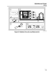
Stakeless Ground Loop Measurement edv007.eps 13 1 2 E H FLUKE 1623 max 50 V plus FLUKE Earth/Ground Tester Setup 3 4 active E H E H Figure 8.
Stakeless Ground Loop Measurement edv007.eps 13 1 2 E H FLUKE 1623 max 50 V plus FLUKE Earth/Ground Tester Setup 3 4 active E H E H Figure 8.
FE 1623 Users Manual
Page 23
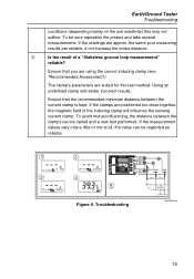
... H >Limit E ES S H 3 S >Limit 4 E ES S H E SH FLUKE 1623 max 50 V P2 S plus FLUKE E/C1 S/P2 H/C2 >20 m >20 m 5 Us Ug Figure 9. the same your measuring results are using the correct inducing clamp (see "Recommended Accessories")! If the clamps are suited for this may not suffice. Troubleshooting edv008.eps 15 Earth/Ground Tester Troubleshooting conditions (depending mainly on...
... H >Limit E ES S H 3 S >Limit 4 E ES S H E SH FLUKE 1623 max 50 V P2 S plus FLUKE E/C1 S/P2 H/C2 >20 m >20 m 5 Us Ug Figure 9. the same your measuring results are using the correct inducing clamp (see "Recommended Accessories")! If the clamps are suited for this may not suffice. Troubleshooting edv008.eps 15 Earth/Ground Tester Troubleshooting conditions (depending mainly on...

FE 1623 Users Manual
Page 25
...: Measuring time: Max. Short-circuit current: > 50 mA Meas. overload: Auxiliary power: Battery life span: Dimensions: Weight: Earth/Ground Tester Specifications developed, designed and manufactured according to DIN ISO 9001 Uext,max = 24 V (DC, AC < 400 Hz), measurement ...x 1.5 V mignon cells alkali-manganese (type AA LR6) typical > 3000 measurements 240 x 180 x 110 mm 1.1 kg (including batteries) RA 3-pole ground resistance measurement Switch position Resolution Measuring range Intrinsic error (IEC 1557-5) Operating error Ra 3-pole 0,001 ... 10 Ω 0,001 Ω ... 19,99...
...: Measuring time: Max. Short-circuit current: > 50 mA Meas. overload: Auxiliary power: Battery life span: Dimensions: Weight: Earth/Ground Tester Specifications developed, designed and manufactured according to DIN ISO 9001 Uext,max = 24 V (DC, AC < 400 Hz), measurement ...x 1.5 V mignon cells alkali-manganese (type AA LR6) typical > 3000 measurements 240 x 180 x 110 mm 1.1 kg (including batteries) RA 3-pole ground resistance measurement Switch position Resolution Measuring range Intrinsic error (IEC 1557-5) Operating error Ra 3-pole 0,001 ... 10 Ω 0,001 Ω ... 19,99...

FE 1623 Users Manual
Page 27
... current: > 50 mA Measuring frequency: 128 Hz (125 Hz on request) Probe resistance (Rs): max. 100 kΩ Auxiliary earth electrode resistance max. 100 kΩ (Rh): Monitoring of Rs, and Rh with current clamp (RA A ) Switch position Resolution...Measurement is not performed if the current through the current clamp is too low. pole selective ground resistance measurement with error indicator. Earth/Ground Tester Specifications Probe resistance (Rs): max. 100 kΩ Auxiliary earth electrode resistance max. 100 kΩ (Rh): Monitoring of Rs, and Rh with external ...
... current: > 50 mA Measuring frequency: 128 Hz (125 Hz on request) Probe resistance (Rs): max. 100 kΩ Auxiliary earth electrode resistance max. 100 kΩ (Rh): Monitoring of Rs, and Rh with current clamp (RA A ) Switch position Resolution...Measurement is not performed if the current through the current clamp is too low. pole selective ground resistance measurement with error indicator. Earth/Ground Tester Specifications Probe resistance (Rs): max. 100 kΩ Auxiliary earth electrode resistance max. 100 kΩ (Rh): Monitoring of Rs, and Rh with external ...

