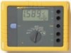
Fluke 1623 and 1625 Geo Earth Ground Testers Datasheet
Page 2
... 250 V rms (pertains to be used over the full working temperature range by double and/or reinforced insulation. The most complete testers The Fluke 1623 and 1625 are rotary switch and START button Instrument is guaranteed for 1 year C1 (IEC 654-1), -5 °C to +45 °...operating elements are distinctive earth ground testers that can be connected and the large rotary switch can perform all inside a rugged Fluke carrying case. 1623 Specifications General Display:1999 digit LCD User interface Robust and waterproof Display with a gloved hand. overload Auxiliary power Battery life...
Fluke 1623 and 1625 Geo Earth Ground Testers Datasheet
Page 3
... error indicator Automatic range selection Max. 100 k7 Max. 100 k7 Measurement is not performed if the current through the current clamp is too low 3 Fluke Corporation 1623 and 1625 GEO Earth Ground Testers RA 3-pole ground resistance measurement (IEC 1557-5) Switch position Resolution Measuring range RA 3-pole 0.001 7 to 10 7 0.001...
Fluke 1623 and 1625 Geo Earth Ground Testers Datasheet
Page 4
... on request) Probe resistance (RS) Auxiliary earth electrode resistance (RH) Monitoring of RS, and RH with the recommended current clamps at the minimum distance specified. 4 Fluke Corporation 1623 and 1625 GEO Earth Ground Testers
Fluke 1623 and 1625 Geo Earth Ground Testers Datasheet
Page 5
... Hz, 60 Hz, 50 Hz, 162/3 Hz or with a mains supply and/or measuring equipment deriving its output voltage directly from the distribution system. 5 Fluke Corporation 1623 and 1625 GEO Earth Ground Testers and 4-pole with/without clip-on current transformer, resistance 2-pole with additional functions Interference voltage and frequency, earthing resistance 3-
Fluke 1623 and 1625 Geo Earth Ground Testers Datasheet
Page 6
... ac 94, 105, 111, 128 Hz selected manually or automatic. (AFC) 55 Hz in function R* 120 dB (162/3, 50 , 60, 400 Hz) Urms = 250 V 6 Fluke Corporation 1623 and 1625 GEO Earth Ground Testers Limits of error Climate class Type of protection Max voltage EMC (Emission Immunity) Quality standard External field influence Auxiliary...
FE 1623 Users Manual
Page 10
... permissible climatic limits without visible external damage etc.). Qualified Personnel are persons familiar with earth electrodes; While a measurement is no earth stake must be touched! Fluke 1623 Users Manual It can be assumed that safe operation is in different installations (e.g. Features • Earth/ground resistance measurements in progress no longer possible if...
FE 1623 Users Manual
Page 11
... A Rotary switch for 6 alcaline batteries (type AA, LR6) or NiCd J batteries (bottom side of measurement functions and ON/OFF. Earth/Ground Tester Safety Regulations 2 1 11 3 FLUKE 1623 max 50 V P2 S 4 5 6 P1 ES 7 plus FLUKE 8 10 9 Figure 1. B START button for starting the selected measurement function. Features and Functions edv001.eps Table 1.
FE 1623 Users Manual
Page 12
Fluke 1623 Users Manual Accessories The following standard accessories were shipped with your Tester: • 6 alkaline AA - type (LR6) batteries • 2 measuring leads 1,5 m • 1 connector cable (for RA 2-pole measurements) • 2 alligator clips • 1 Users Manual Carrying Case The part number for the carrying case for the 1623 Earth/Ground Tester and accessories such as the current probes is 2583565. 4
FE 1623 Users Manual
Page 13
... Ground Tester - Basic (Includes manual, 2 leads and 2 clips) Earth Ground Tester - Fully Loaded (Includes manual, 2 leads and 2 clips, ES162P4, EI-1623) Service Replacement Kit (Includes 2 Leads, 2 Clips) Stake Set for 3 Pole Measurement (Includes three stakes, one 25 m cable reel, one 50 m cable ... (320mm) Spilt Core Transformer Earth Stake Cable Reel w/25m Wire Cable Reel w/50m Wire 1623 Users Manual Item/Part Number Fluke-1623 Fluke-1623 Kit Fluke-162x-7001 ES-162P3 ES-162P4 EI-1623 EI-162X 2630254 EI-162AC EI-162BN 2630222 2630231 2630246 2560327 5 Models and Accessories Table ...
FE 1623 Users Manual
Page 14
Open battery compartment. 4. Switch off instrument. 2. Insert batteries. Fluke 1623 Users Manual Setup W Warning Please, read carefully the "safety regulations" before powering up the instrument. Inserting Batteries edv002.eps 6 Close battery compartment. 1 2 3 4 + Figure 2. Disconnect all test leads. 3. Inserting Batteries Refer to Figure 2 and following these steps: 1. If you have problems see section "Troubleshooting".
FE 1623 Users Manual
Page 17
.... Display as shown below . Place 2 ground stakes in progress. The "active" symbol indicates that a measurement is turned. 1 2 E ES S H FLUKE 1623 Earth/Ground Tester max 50 V P2 S P1 ES/P1 ES E/C1 S/P2 H/C2 plus FLUKE E >20 m >20 m 3 4 active E ES S H E ES S H Figure 5. B Connect test leads. Earth/Ground Tester Setup RA 4-pole Measurements Refer to...
FE 1623 Users Manual
Page 18
...the ground system to be at least 20 m! The "active" symbol indicates that measurement is turned. 1 2 E SH max 50 V P2 S plus FLUKE 3 4 active E SH E SH edv005.eps Figure 6. Minimum distance between earth electrode (E/C1), probe (S/P2) and auxiliary earth (H/C2) should be ... as shown below. Connect stakes with adapter cable as shown. Connect current clamp with 25 m and 50 m wires to Figure 6. Fluke 1623 Users Manual RA 3-pole Selective Earth Resistance Measurement with Current Clamp The RA 3-pole Selective Earth Resistance Measurement with Current Clamp 10 RA...
FE 1623 Users Manual
Page 20
.... B Connect current clamps. Clamp both current clamps around the earth electrode, which will subsequently be measured. The "active" symbol indicates that measurement is turned. 12 Fluke 1623 Users Manual Stakeless Ground Loop Measurement Refer to terminals H/C2 and E/C1 using the adapter cable (sensing current clamp). A Select function D Display as shown. D Symbol...
FE 1623 Users Manual
Page 21
Stakeless Ground Loop Measurement edv007.eps 13 1 2 E H FLUKE 1623 max 50 V plus FLUKE Earth/Ground Tester Setup 3 4 active E H E H Figure 8.
FE 1623 Users Manual
Page 22
... stake. Hint: Reposition probe (S/P2) and restart measurement. If not, a reset occurs. Hint: Replace batteries. Table 3. The measurement is blocked (see "Technical data" for steps 1-5. Fluke 1623 Users Manual Troubleshooting Follow the steps in Table 4 and refer to the instrument is too high, usually from leakage currents in some environmental 14 Weak...
FE 1623 Users Manual
Page 23
... are suited for this may not suffice. The clamp's parameters are approx. To be regarded as reliable. 1 U ext >Limit 2 E SH H >Limit E ES S H 3 S >Limit 4 E ES S H E SH FLUKE 1623 max 50 V P2 S plus FLUKE E/C1 S/P2 H/C2 >20 m >20 m 5 Us Ug Figure 9. To avoid mutual influencing, the distance between the current clamp is kept.
FE 1623 Users Manual
Page 24
...;C, 5 %...95 % RH Protective type: IP56 for case, IP40 for battery door according to modify specifications without notice for the purpose of use. Temp. Fluke 1623 Users Manual Specifications Note Fluke reserves the right to EN 60529 Safety Protection by using the temperature coefficient to the reference temperature range and is guaranteed for 1 year.
FE 1623 Users Manual
Page 26
... error Ra 4-pole 0,001 ... 10 Ω 0,001 Ω ... 19,99 kΩ ±(2% rdg + 3 d) ±(5% rdg + 3 d) Measuring principle: Current/voltage measurement Measuring voltage: Um = 48 Vac. Fluke 1623 Users Manual Automatic range selection.
FE 1623 Users Manual
Page 28
... in closed loops using two current transformers Measuring voltage: Um = 48 VAC (primary) Measuring frequency: 128 Hz (125 Hz on request) Noise current (Iext): max. Fluke 1623 Users Manual D Stakeless ground loop measurement ( ) Switch position Resolution Measuring range Intrinsic error Operating error Ra 4-pole 0.001 ... D 0.1 Ω 0.001 Ω .. 199.9 Ω ±(7% rdg...