Calibration Guide
Page 1
All product names are subject to change without notice. Specifications are trademarks of their respective companies. All rights reserved. 123B/124B/125B Industrial ScopeMeter Calibration Manual May 2016 ©2016 Fluke Corporation.
All product names are subject to change without notice. Specifications are trademarks of their respective companies. All rights reserved. 123B/124B/125B Industrial ScopeMeter Calibration Manual May 2016 ©2016 Fluke Corporation.

Calibration Guide
Page 2
...OF DATA, ARISING FROM ANY CAUSE OR THEORY. Box 1186 5602 BD Eindhoven The Netherlands 11/99 Fluke warrants that service center, with its functional specifications for damage in material and workmanship under normal use outside the product's specified rating, or normal wear... NOT LIMITED TO ANY IMPLIED WARRANTY OF MERCHANTABILITY OR FITNESS FOR A PARTICULAR PURPOSE. P.O. LIMITED WARRANTY AND LIMITATION OF LIABILITY Each Fluke product is warranted to every buyer. Following warranty repair, the product will provide an estimate of operation or handling, including overvoltage...
...OF DATA, ARISING FROM ANY CAUSE OR THEORY. Box 1186 5602 BD Eindhoven The Netherlands 11/99 Fluke warrants that service center, with its functional specifications for damage in material and workmanship under normal use outside the product's specified rating, or normal wear... NOT LIMITED TO ANY IMPLIED WARRANTY OF MERCHANTABILITY OR FITNESS FOR A PARTICULAR PURPOSE. P.O. LIMITED WARRANTY AND LIMITATION OF LIABILITY Each Fluke product is warranted to every buyer. Following warranty repair, the product will provide an estimate of operation or handling, including overvoltage...

Calibration Guide
Page 3
Table of Contents Title Page Introduction 1 How to Contact Fluke 1 Safety Information 2 Specifications 4 Dual Input Oscilloscope 4 Cursor Readout (124B, 125B 8 Power Quality (125B 9 Field Bus Measurements (125B 9 Miscellaneous 10 Environmental 10 Required Equipment 12 Performance Verification 12 Test Preparation 12 Input A ...Test 25 Input A and Input B Volts Peak Measurements Test 25 Input A and B Phase Measurements Test 27 Harmonics Test (125B 27 Input A and B High Voltage AC/DC Accuracy Test 28 Resistance Measurements Test 30 Continuity Function Test 30 Diode Function ...
Table of Contents Title Page Introduction 1 How to Contact Fluke 1 Safety Information 2 Specifications 4 Dual Input Oscilloscope 4 Cursor Readout (124B, 125B 8 Power Quality (125B 9 Field Bus Measurements (125B 9 Miscellaneous 10 Environmental 10 Required Equipment 12 Performance Verification 12 Test Preparation 12 Input A ...Test 25 Input A and Input B Volts Peak Measurements Test 25 Input A and B Phase Measurements Test 27 Harmonics Test (125B 27 Input A and B High Voltage AC/DC Accuracy Test 28 Resistance Measurements Test 30 Continuity Function Test 30 Diode Function ...

Calibration Guide
Page 12
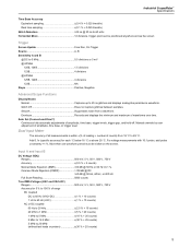
... 4 GS/s Real time sampling 1 μs to 400 Hz Vertical Accuracy 1 % + 0.05 range/div) Max. 123B/124B/125B Calibration Manual Specifications Dual Input Oscilloscope Vertical Frequency Response DC Coupled without probes and test leads (with BB120) 125B, 124B DC to 40 MHz (-3 dB) 123B DC to 20 MHz (-3 dB) with STL120-IV 1:1 shielded test...
... 4 GS/s Real time sampling 1 μs to 400 Hz Vertical Accuracy 1 % + 0.05 range/div) Max. 123B/124B/125B Calibration Manual Specifications Dual Input Oscilloscope Vertical Frequency Response DC Coupled without probes and test leads (with BB120) 125B, 124B DC to 40 MHz (-3 dB) 123B DC to 20 MHz (-3 dB) with STL120-IV 1:1 shielded test...
Calibration Guide
Page 13
... On Trigger Source A, B Sensitivity A and B @ DC to 5 MHz 0.5 divisions or 5 mV @ 40 MHz 125B, 124B 1.5 divisions 123B 4 divisions @ 60 MHz 125B, 124B 4 divisions 123B NA Slope Positive, Negative Advanced Scope Functions Display Modes Normal Captures up to 25 ns glitches and ...:1 probe, add probe uncertainty +1 %. Envelope Records and displays the minimum and maximum of amplitude, time base, trigger levels, trigger gap, and hold-off. Add 0.1x (specific accuracy) for 5 % to 100 % of amplitude, time base, or trigger level. Input A and Input B DC Voltage (VDC) Ranges 500 mV, 5 V, 50 ...
... On Trigger Source A, B Sensitivity A and B @ DC to 5 MHz 0.5 divisions or 5 mV @ 40 MHz 125B, 124B 1.5 divisions 123B 4 divisions @ 60 MHz 125B, 124B 4 divisions 123B NA Slope Positive, Negative Advanced Scope Functions Display Modes Normal Captures up to 25 ns glitches and ...:1 probe, add probe uncertainty +1 %. Envelope Records and displays the minimum and maximum of amplitude, time base, trigger levels, trigger gap, and hold-off. Add 0.1x (specific accuracy) for 5 % to 100 % of amplitude, time base, or trigger level. Input A and Input B DC Voltage (VDC) Ranges 500 mV, 5 V, 50 ...

Calibration Guide
Page 15
Industrial ScopeMeter Specifications with iFlex clamp Ranges 20 A/division Maximum Current 75 A @ 40 Hz to 300 Hz Frequency derating: I * F
Industrial ScopeMeter Specifications with iFlex clamp Ranges 20 A/division Maximum Current 75 A @ 40 Hz to 300 Hz Frequency derating: I * F

Calibration Guide
Page 17
...±(30 % + 5 counts) Frequency of Meter measurements over time or as Chart recorder display that plots all the captured samples. Industrial ScopeMeter Specifications Recorder The recorder captures meter readings in Meter Recorder mode or continuously captures waveform samples in Amp and Watt 10 % Field Bus Measurements... sample/s Record Size Internal memory 400 M samples Recorded Time Span internal memory 15 minutes at 500 μs/div 11 hours at 20 ms/div 125B, 124B Record Size SD card 15 G samples Recorded Time Span SD card 11 hours at 500 μs/div 14 days at 20 ms/div...
...±(30 % + 5 counts) Frequency of Meter measurements over time or as Chart recorder display that plots all the captured samples. Industrial ScopeMeter Specifications Recorder The recorder captures meter readings in Meter Recorder mode or continuously captures waveform samples in Amp and Watt 10 % Field Bus Measurements... sample/s Record Size Internal memory 400 M samples Recorded Time Span internal memory 15 minutes at 500 μs/div 11 hours at 20 ms/div 125B, 124B Record Size SD card 15 G samples Recorded Time Span SD card 11 hours at 500 μs/div 14 days at 20 ms/div...

Calibration Guide
Page 19
Industrial ScopeMeter Specifications Electromagnetic Compatibility (EMC) International IEC 61326-1: Industrial CISPR 11: Group 1, Class A Group 1: Equipment has intentionally generated and/or uses conductively-coupled radio frequency energy that ... or with leads 600 Vrms CAT IV for derating, see Figure 1. Max. Max. Voltage Between Test Tool and STL120-IV Reference and Earth Ground The Fluke 12xB series, including standard accessories, conforms to the EEC directive 2004/108/EC for EMC immunity, as defined by CISPR 11 can occur when the...
Industrial ScopeMeter Specifications Electromagnetic Compatibility (EMC) International IEC 61326-1: Industrial CISPR 11: Group 1, Class A Group 1: Equipment has intentionally generated and/or uses conductively-coupled radio frequency energy that ... or with leads 600 Vrms CAT IV for derating, see Figure 1. Max. Max. Voltage Between Test Tool and STL120-IV Reference and Earth Ground The Fluke 12xB series, including standard accessories, conforms to the EEC directive 2004/108/EC for EMC immunity, as defined by CISPR 11 can occur when the...
Calibration Guide
Page 20
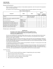
...Calibration Tests Adjustment X X X X X X X X X X X X X X X Performance Verification XW Warning Procedures in illustrations) Used on the specifications. The values given here are listed for each test point, wait for the verification tests and calibration adjustment of the tests vary because the 124B...Turn on the same measurement principles. 123B/124B/125B Calibration Manual Required Equipment Before you start the verification procedures or make calibration adjustments, refer to do not perform any of the Test Tool's specifications. See Table 2 for a list of ...
...Calibration Tests Adjustment X X X X X X X X X X X X X X X Performance Verification XW Warning Procedures in illustrations) Used on the specifications. The values given here are listed for each test point, wait for the verification tests and calibration adjustment of the tests vary because the 124B...Turn on the same measurement principles. 123B/124B/125B Calibration Manual Required Equipment Before you start the verification procedures or make calibration adjustments, refer to do not perform any of the Test Tool's specifications. See Table 2 for a list of ...

Calibration Guide
Page 42
...: 1. The first step is: WarmingUp (CL0200) :BUSY 00:29:59 The warming-up : 1. Final Calibration It is not started . 123B/124B/125B Calibration Manual Table 12. Select the previous step. Starting at any other pre-calibration steps are invalid. The other step will make the calibration invalid...to Final Calibration. It does not necessarily mean that the unit will make the calibration invalid. This means that the unit meets the specifications related to wrong input signal(s) or because the Test Tool is not started . Select the next step. The procedure takes about 60 ...
...: 1. The first step is: WarmingUp (CL0200) :BUSY 00:29:59 The warming-up : 1. Final Calibration It is not started . 123B/124B/125B Calibration Manual Table 12. Select the previous step. Starting at any other pre-calibration steps are invalid. The other step will make the calibration invalid...to Final Calibration. It does not necessarily mean that the unit will make the calibration invalid. This means that the unit meets the specifications related to wrong input signal(s) or because the Test Tool is not started . Select the next step. The procedure takes about 60 ...

Calibration Guide
Page 48
... to start the calibration. 8. Remove all test leads from the Test Tool inputs. Connect the Test Tool to the Calibrator as shown in the Specifications section. 3. Capacitance Gain Calibration Points Cap Gain (CL 0565) Cap Gain (CL 0566) Cap Gain (CL 0567) Cap Gain (CL 0568) Cap ...50 nF 50 nF 5 μF 50 μF 500 μF Input Value Save Calibration Data and Exit To save and exit. 123B/124B/125B Calibration Manual Capacitance Clamp and Zero To do the Capacitance Gain calibration for each Calibration Step in not valid, return to Maintenance mode. 40 Push...
... to start the calibration. 8. Remove all test leads from the Test Tool inputs. Connect the Test Tool to the Calibrator as shown in the Specifications section. 3. Capacitance Gain Calibration Points Cap Gain (CL 0565) Cap Gain (CL 0566) Cap Gain (CL 0567) Cap Gain (CL 0568) Cap ...50 nF 50 nF 5 μF 50 μF 500 μF Input Value Save Calibration Data and Exit To save and exit. 123B/124B/125B Calibration Manual Capacitance Clamp and Zero To do the Capacitance Gain calibration for each Calibration Step in not valid, return to Maintenance mode. 40 Push...
