Fluke ScopeMeter Product Datasheet
Page 2
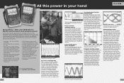
...190B Series: Speed, performance and analysis power For the more demanding applications, the ScopeMeter 190 Series highperformance oscilloscopes offer specifications usually found on top-end bench instruments. The spectrum analysis function is included for engineers who need the full ...-and-View™ automatic trig- On-screen color labels, measurements and warnings are clearly linked to specific waveforms. See dynamic signal behavior instantaneously The Digital Persistence mode (Fluke 190C) helps to find tiny details in a long waveform, for example, in-frequency dividers and clocked...
...190B Series: Speed, performance and analysis power For the more demanding applications, the ScopeMeter 190 Series highperformance oscilloscopes offer specifications usually found on top-end bench instruments. The spectrum analysis function is included for engineers who need the full ...-and-View™ automatic trig- On-screen color labels, measurements and warnings are clearly linked to specific waveforms. See dynamic signal behavior instantaneously The Digital Persistence mode (Fluke 190C) helps to find tiny details in a long waveform, for example, in-frequency dividers and clocked...
Fluke ScopeMeter Product Datasheet
Page 3
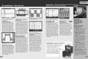
... actual signal against a reference template Waveform Pass/Fail Testing "Waveform reference" allows an acquired trace to the main instrument type number, e.g., Fluke 199C/S (see it . Incorrect settings show unstable and sometimes incorrect results. Software and cable come as separate items, or as a ... All inputs are instantly recognized and settings adjusted for visual comparisons, or it is measured on a specific, user identified portion of the waveform using the cursors of the Fluke 190C to kV, making the 190C and 190B ScopeMeter ideal for waveform comparison and "Pass/Fail" ...
... actual signal against a reference template Waveform Pass/Fail Testing "Waveform reference" allows an acquired trace to the main instrument type number, e.g., Fluke 199C/S (see it . Incorrect settings show unstable and sometimes incorrect results. Software and cable come as separate items, or as a ... All inputs are instantly recognized and settings adjusted for visual comparisons, or it is measured on a specific, user identified portion of the waveform using the cursors of the Fluke 190C to kV, making the 190C and 190B ScopeMeter ideal for waveform comparison and "Pass/Fail" ...
Fluke ScopeMeter Product Datasheet
Page 4
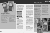
...and drip proof case assures long life and reliable operation in the harshest industrial environments. (See technical specifications for the maintenance engineer who deals with motor drives and inverters. Fluke 125 is as easy as connecting to the test point and letting the scope do the job ...of just 1.2 kg (2.64 lbs) make a simple resistance measurement. The handheld format and the weight of 20 MHz (Fluke 123) or 40 MHz (Fluke 124, 125) the Fluke 120 Series will capture and display almost any signal. Via the optically isolated interface, the ScopeMeter 120 can be safely connected ...
...and drip proof case assures long life and reliable operation in the harshest industrial environments. (See technical specifications for the maintenance engineer who deals with motor drives and inverters. Fluke 125 is as easy as connecting to the test point and letting the scope do the job ...of just 1.2 kg (2.64 lbs) make a simple resistance measurement. The handheld format and the weight of 20 MHz (Fluke 123) or 40 MHz (Fluke 124, 125) the Fluke 120 Series will capture and display almost any signal. Via the optically isolated interface, the ScopeMeter 120 can be safely connected ...
Fluke ScopeMeter Product Datasheet
Page 5
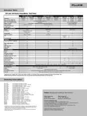
... • • - amps - diode - Ordering information Fluke 199C Fluke 199C/S Fluke 196C Fluke 196C/S Fluke 199B Fluke 199B/S Fluke 196B Fluke 196B/S Fluke 192B Fluke 192B/S Fluke 125 Fluke 125/S Fluke 124 Fluke 124/S Fluke 123 Fluke 123/S SCC190 SCC120 OC4USB PM9080 SW90W Color ScopeMeter (200 MHz /... mV/div. to change without notice. Color Monochrome Monochrome Digital persistence with Fluke 125 and Fluke 124) Detailed technical specifications and optional accessories can be found in the technical datasheet or on standard ...
... • • - amps - diode - Ordering information Fluke 199C Fluke 199C/S Fluke 196C Fluke 196C/S Fluke 199B Fluke 199B/S Fluke 196B Fluke 196B/S Fluke 192B Fluke 192B/S Fluke 125 Fluke 125/S Fluke 124 Fluke 124/S Fluke 123 Fluke 123/S SCC190 SCC120 OC4USB PM9080 SW90W Color ScopeMeter (200 MHz /... mV/div. to change without notice. Color Monochrome Monochrome Digital persistence with Fluke 125 and Fluke 124) Detailed technical specifications and optional accessories can be found in the technical datasheet or on standard ...
FE 123 & 124 Users Manual
Page 3
...services are warranted for its functional specifications for 90 days and that software will operate substantially in accordance with a description of operation or handling. Fluke warrants that software will be error free or operate without interruption. Fluke reserves the right to the Buyer ... postage and insurance prepaid (FOB Destination), to Buyer, transportation prepaid (FOB Destination). To obtain warranty service, contact your nearest Fluke authorized service center or send the product, with its accessories. If any provision of this warranty on behalf of a defective ...
...services are warranted for its functional specifications for 90 days and that software will operate substantially in accordance with a description of operation or handling. Fluke warrants that software will be error free or operate without interruption. Fluke reserves the right to the Buyer ... postage and insurance prepaid (FOB Destination), to Buyer, transportation prepaid (FOB Destination). To obtain warranty service, contact your nearest Fluke authorized service center or send the product, with its accessories. If any provision of this warranty on behalf of a defective ...
FE 123 & 124 Users Manual
Page 7
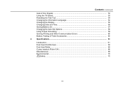
Contents (continued) Goal of this Chapter ...53 Using the Tilt Stand...53 Resetting the Test Tool 54 Changing the Information Language 54 Changing the Display ...55 Changing Date and Time 56 Saving Battery Life ...57 Changing the Auto Set Options 58 Using Proper Grounding 59 Solving Printing and Other Communication Errors 60 Battery Testing of Fluke Accessories 60 4 Specifications...61 Introduction ...61 Dual Input Oscilloscope 62 Dual Input Meter...65 Cursor readout (Fluke 124 68 Miscellaneous ...69 Environmental ...70 Safety ...70 iii
Contents (continued) Goal of this Chapter ...53 Using the Tilt Stand...53 Resetting the Test Tool 54 Changing the Information Language 54 Changing the Display ...55 Changing Date and Time 56 Saving Battery Life ...57 Changing the Auto Set Options 58 Using Proper Grounding 59 Solving Printing and Other Communication Errors 60 Battery Testing of Fluke Accessories 60 4 Specifications...61 Introduction ...61 Dual Input Oscilloscope 62 Dual Input Meter...65 Cursor readout (Fluke 124 68 Miscellaneous ...69 Environmental ...70 Safety ...70 iii
FE 123 & 124 Users Manual
Page 12
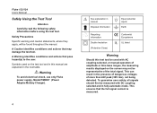
...conditions and actions that may not be used on the screen may damage the test tool. Warning To avoid electrical shock, use only Fluke power supply, Model PM8907 (Power Adapter/Battery Charger). 4 See explanation in manual Disposal information Equal potential inputs Earth Recycling information Double ...To guarantee user safety, all signals should first be found throughout the manual. This can result in the next table. Safety Precautions Specific warning and caution statements, where they apply, will be measured with AC coupling selected, or manual operation of more than 42V peak...
...conditions and actions that may not be used on the screen may damage the test tool. Warning To avoid electrical shock, use only Fluke power supply, Model PM8907 (Power Adapter/Battery Charger). 4 See explanation in manual Disposal information Equal potential inputs Earth Recycling information Double ...To guarantee user safety, all signals should first be found throughout the manual. This can result in the next table. Safety Precautions Specific warning and caution statements, where they apply, will be measured with AC coupling selected, or manual operation of more than 42V peak...

FE 123 & 124 Users Manual
Page 39
Select number 135. Select SELECT Highlight POSITIVE. Accept the video trigger selections . 31 To measure on a selected video line, continue from point of the previous example as follows: Highlight SELECT 1 Using The Test Tool Triggering on a Specific Video Line To view a specific video line in more detail you can select the line number. Triggering on a Waveform Pressing selects the line number function. To choose line 135, do the following: Enable video line selection.
Select number 135. Select SELECT Highlight POSITIVE. Accept the video trigger selections . 31 To measure on a selected video line, continue from point of the previous example as follows: Highlight SELECT 1 Using The Test Tool Triggering on a Specific Video Line To view a specific video line in more detail you can select the line number. Triggering on a Waveform Pressing selects the line number function. To choose line 135, do the following: Enable video line selection.
FE 123 & 124 Users Manual
Page 69
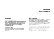
... impair protection provided by the equipment. 61 Safety Characteristics The test tool has been designed and tested in accordance with the stated tolerance. Chapter 4 Specifications Introduction Performance Characteristics FLUKE guarantees the properties expressed in numerical values with Standards ANSI/ISA S82.01-1994, EN 61010.1 (1993) (IEC 1010-1), CAN/CSA-C22.2 No...
... impair protection provided by the equipment. 61 Safety Characteristics The test tool has been designed and tested in accordance with the stated tolerance. Chapter 4 Specifications Introduction Performance Characteristics FLUKE guarantees the properties expressed in numerical values with Standards ANSI/ISA S82.01-1994, EN 61010.1 (1993) (IEC 1010-1), CAN/CSA-C22.2 No...
FE 123 & 124 Users Manual
Page 70
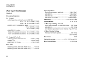
... MHz (-3 dB) with STL120 1:1 shielded test leads DC to 12.5 MHz (-3 dB) DC to 20 MHz (-6 dB) with VP40 10:1 probe Fluke 123 (optional accessory): DC to 20 MHz (-3 dB) Fluke 124 (standard accessory): DC to 40 MHz (-3 dB) AC Coupled (LF roll off): excluding probes and test leads 10 Hz (-3 dB) with...
... MHz (-3 dB) with STL120 1:1 shielded test leads DC to 12.5 MHz (-3 dB) DC to 20 MHz (-6 dB) with VP40 10:1 probe Fluke 123 (optional accessory): DC to 20 MHz (-3 dB) Fluke 124 (standard accessory): DC to 40 MHz (-3 dB) AC Coupled (LF roll off): excluding probes and test leads 10 Hz (-3 dB) with...
FE 123 & 124 Users Manual
Page 71
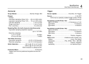
Horizontal Scope Modes Normal, Single, Roll Ranges Normal: equivalent sampling (Fluke 123) ..... 20 ns to 500 ns/div equivalent sampling (Fluke 124) ..... 10 ns to 500 ns/div real time sampling 1 µs to 5 s/div Single (real time 1 µs to 5 s/...the screen. 4 Specifications Dual Input Oscilloscope Trigger Screen Update Free Run, On Trigger Source A, B, EXT EXTernal via optically isolated trigger probe ITP120 (optional accessory) Sensitivity A and B (Fluke 123) @ DC to 5 MHz 0.5 divisions or 5 mV @ 25 MHz 1.5 divisions @ 40 MHz 4 divisions Sensitivity A and B (Fluke 124) @ DC to...
Horizontal Scope Modes Normal, Single, Roll Ranges Normal: equivalent sampling (Fluke 123) ..... 20 ns to 500 ns/div equivalent sampling (Fluke 124) ..... 10 ns to 500 ns/div real time sampling 1 µs to 5 s/div Single (real time 1 µs to 5 s/...the screen. 4 Specifications Dual Input Oscilloscope Trigger Screen Update Free Run, On Trigger Source A, B, EXT EXTernal via optically isolated trigger probe ITP120 (optional accessory) Sensitivity A and B (Fluke 123) @ DC to 5 MHz 0.5 divisions or 5 mV @ 25 MHz 1.5 divisions @ 40 MHz 4 divisions Sensitivity A and B (Fluke 124) @ DC to...
FE 123 & 124 Users Manual
Page 73
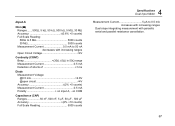
...% +25 counts) 5 MHz to 28 °C. Add 0.1x (specific accuracy) for 5 to 100% of full scale Full Scale Reading 500 counts Frequency (Hz) Ranges 1 Hz, 10 Hz, 100 Hz, 1 kHz, 10 kHz, 100 kHz,1 MHz, 10 MHz, and 50 MHz (Fluke 123) or 70MHz (Fluke 124) Frequency Range in Continuous Autoset 15 Hz (1 Hz...
...% +25 counts) 5 MHz to 28 °C. Add 0.1x (specific accuracy) for 5 to 100% of full scale Full Scale Reading 500 counts Frequency (Hz) Ranges 1 Hz, 10 Hz, 100 Hz, 1 kHz, 10 kHz, 100 kHz,1 MHz, 10 MHz, and 50 MHz (Fluke 123) or 70MHz (Fluke 124) Frequency Range in Continuous Autoset 15 Hz (1 Hz...
FE 123 & 124 Users Manual
Page 75
... Current 0.5 mA Polarity on COM Capacitance (CAP) Ranges 50 nF, 500 nF, 5 µF, 50 µF, 500 µF Accuracy 2% +10 counts) Full Scale Reading 5000 counts 4 Specifications Dual Input Meter Measurement Current 5 µA to 50 nA decreases with parasitic serial and parallel resistance cancellation. 67
... Current 0.5 mA Polarity on COM Capacitance (CAP) Ranges 50 nF, 500 nF, 5 µF, 50 µF, 500 µF Accuracy 2% +10 counts) Full Scale Reading 5000 counts 4 Specifications Dual Input Meter Measurement Current 5 µA to 50 nA decreases with parasitic serial and parallel resistance cancellation. 67
FE 123 & 124 Users Manual
Page 77
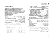
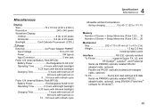
... 60 hours with test tool on 12 .. 19 hours with refresh cycle 4 Specifications Miscellaneous Allowable ambient temperature: during charging 0 to 45 °C (32 to 113 °F) Memory Number of Screen + Setup Memories (Fluke 123) .... 10 Number of Screen + Setup Memories (Fluke 124) .... 20 Mechanical Size 232 x 115 x 50 mm (9.1 x 4.5 x 2 in) Weight 1.2 kg (2.5 lbs) including...
... 60 hours with test tool on 12 .. 19 hours with refresh cycle 4 Specifications Miscellaneous Allowable ambient temperature: during charging 0 to 45 °C (32 to 113 °F) Memory Number of Screen + Setup Memories (Fluke 123) .... 10 Number of Screen + Setup Memories (Fluke 124) .... 20 Mechanical Size 232 x 115 x 50 mm (9.1 x 4.5 x 2 in) Weight 1.2 kg (2.5 lbs) including...

FE 123 & 124 Users Manual
Page 79
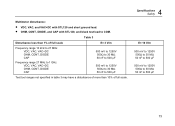
Input Voltage v.s. Frequency for VP40 10:1 Voltage Probe 71 Max. Frequency for BB120 and STL120 Figure 4-2. Input Voltage v.s. Max. 4 Specifications Safety Figure 4-1.
Input Voltage v.s. Frequency for VP40 10:1 Voltage Probe 71 Max. Frequency for BB120 and STL120 Figure 4-2. Input Voltage v.s. Max. 4 Specifications Safety Figure 4-1.
FE 123 & 124 Users Manual
Page 81
...; to 30 MΩ 50 nF to 500 µF Test tool ranges not specified in table 3 may have a disturbance of more than 10% of full scale. 4 Specifications Safety E= 10 V/m 500 mV to 1250V 500Ω to 30 MΩ 50 nF to 500 µF 500 mV to 1250V 500Ω to 30 MΩ...
...; to 30 MΩ 50 nF to 500 µF Test tool ranges not specified in table 3 may have a disturbance of more than 10% of full scale. 4 Specifications Safety E= 10 V/m 500 mV to 1250V 500Ω to 30 MΩ 50 nF to 500 µF 500 mV to 1250V 500Ω to 30 MΩ...
FE 123 & 124 Users Manual
Page 86
...Shock, 70 Single Shot, 23 Slope, 27, 63 Slow Signals, 25 Smooth, 20, 64 Soft Carrying Case, 52 Software, 52 78 Software Version, 49 Specifications, 61 Stable Reading, 16 Stand, 53 STL120 Test Leads, 50 Storing, 43 SW90W Software, 41, 52 -T- Unpacking, 2 User Manual, 51 Using a... Printer, 39 Using FlukeView Software, 41 -V- Fluke 123/124 Users Manual RS-232 Adapter/Cable, 39, 41, 52 RS-232 Communication Errors, 60 -S- Zero Reference, 17 Waveform Area, 10 -Z- Temperature Measurement, 66 ...
...Shock, 70 Single Shot, 23 Slope, 27, 63 Slow Signals, 25 Smooth, 20, 64 Soft Carrying Case, 52 Software, 52 78 Software Version, 49 Specifications, 61 Stable Reading, 16 Stand, 53 STL120 Test Leads, 50 Storing, 43 SW90W Software, 41, 52 -T- Unpacking, 2 User Manual, 51 Using a... Printer, 39 Using FlukeView Software, 41 -V- Fluke 123/124 Users Manual RS-232 Adapter/Cable, 39, 41, 52 RS-232 Communication Errors, 60 -S- Zero Reference, 17 Waveform Area, 10 -Z- Temperature Measurement, 66 ...
