Fluke ScopeMeter Product Datasheet
Page 4
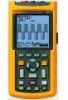
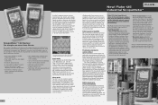
...mobility Up to seven hours of battery operation frees you want to focus on the Fluke 125. The Fluke 125 validates the quality of applied frequencies, including those seen with Fluke 124 and 125 for measurements on 600 V CAT III industrial power systems. Using the VPS40...simultaneously measuring and checking waveforms. The unique Connect-and-View™ triggering automatically displays stable waveforms of 20 MHz (Fluke 123) or 40 MHz (Fluke 124, 125) the Fluke 120 Series will capture and display almost any signal. The ScopeMeter 120 Series includes a multimeter on a network segment...
...mobility Up to seven hours of battery operation frees you want to focus on the Fluke 125. The Fluke 125 validates the quality of applied frequencies, including those seen with Fluke 124 and 125 for measurements on 600 V CAT III industrial power systems. Using the VPS40...simultaneously measuring and checking waveforms. The unique Connect-and-View™ triggering automatically displays stable waveforms of 20 MHz (Fluke 123) or 40 MHz (Fluke 124, 125) the Fluke 120 Series will capture and display almost any signal. The ScopeMeter 120 Series includes a multimeter on a network segment...
Fluke ScopeMeter Product Datasheet
Page 5
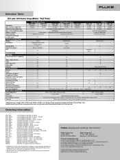
... power PC and printer interface Warranty 190C ScopeMeter Series 190B ScopeMeter Series 120 Series Fluke 199C Fluke 196C Fluke 199B Fluke 196B Fluke 192B Fluke 125 Fluke 124 Fluke 123 200 MHz 100 MHz 200 MHz 100 MHz 60 MHz 40 MHz 40 MHz ...Bandwidth Max. to 100 V/div. 5 mV/div. harmonics - Ordering information Fluke 199C Fluke 199C/S Fluke 196C Fluke 196C/S Fluke 199B Fluke 199B/S Fluke 196B Fluke 196B/S Fluke 192B Fluke 192B/S Fluke 125 Fluke 125/S Fluke 124 Fluke 124/S Fluke 123 Fluke 123/S SCC190 SCC120 OC4USB PM9080 SW90W Color ScopeMeter (200 MHz / 2.5 GS/s) ...
... power PC and printer interface Warranty 190C ScopeMeter Series 190B ScopeMeter Series 120 Series Fluke 199C Fluke 196C Fluke 199B Fluke 196B Fluke 192B Fluke 125 Fluke 124 Fluke 123 200 MHz 100 MHz 200 MHz 100 MHz 60 MHz 40 MHz 40 MHz ...Bandwidth Max. to 100 V/div. 5 mV/div. harmonics - Ordering information Fluke 199C Fluke 199C/S Fluke 196C Fluke 196C/S Fluke 199B Fluke 199B/S Fluke 196B Fluke 196B/S Fluke 192B Fluke 192B/S Fluke 125 Fluke 125/S Fluke 124 Fluke 124/S Fluke 123 Fluke 123/S SCC190 SCC120 OC4USB PM9080 SW90W Color ScopeMeter (200 MHz / 2.5 GS/s) ...

Fluke 123 and 124 Scopemeter Datasheet
Page 1
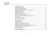
... all in a while - Incorrect settings show unstable and sometimes incorrect results. And using FlukeView software. Ordering information FLUKE-123/003 Industrial ScopeMeter 20 MHz FLUKE-123/003S Industrial ScopeMeter 20 MHz with the for direct print-out or to a PC for an instant, stable display...both meter reading and waveform at test objects of every dimension. operation • Shielded test leads for Verifying CAN bus signals with Fluke 124) • 600 V CAT III safety certified • Optically isolated RS-232 interface • Rugged, compact case ctrical Sa ...
... all in a while - Incorrect settings show unstable and sometimes incorrect results. And using FlukeView software. Ordering information FLUKE-123/003 Industrial ScopeMeter 20 MHz FLUKE-123/003S Industrial ScopeMeter 20 MHz with the for direct print-out or to a PC for an instant, stable display...both meter reading and waveform at test objects of every dimension. operation • Shielded test leads for Verifying CAN bus signals with Fluke 124) • 600 V CAT III safety certified • Optically isolated RS-232 interface • Rugged, compact case ctrical Sa ...

FE 123 & 124 Users Manual
Page 1
Users Manual All rights reserved. All product names are trademarks of their respective companies. ® Fluke 123/124 Industrial ScopeMeter GB Sep 2002 © 2002 Fluke Corporation.
Users Manual All rights reserved. All product names are trademarks of their respective companies. ® Fluke 123/124 Industrial ScopeMeter GB Sep 2002 © 2002 Fluke Corporation.
FE 123 & 124 Users Manual
Page 6
Fluke 123/124 Users Manual Freezing the Screen...16 Holding a Stable Reading 16 Making Relative Measurements 17 Selecting Auto/Manual Ranges 18 Changing the Graphic Representation on the ...
Fluke 123/124 Users Manual Freezing the Screen...16 Holding a Stable Reading 16 Making Relative Measurements 17 Selecting Auto/Manual Ranges 18 Changing the Graphic Representation on the ...
FE 123 & 124 Users Manual
Page 7
Contents (continued) Goal of this Chapter ...53 Using the Tilt Stand...53 Resetting the Test Tool 54 Changing the Information Language 54 Changing the Display ...55 Changing Date and Time 56 Saving Battery Life ...57 Changing the Auto Set Options 58 Using Proper Grounding 59 Solving Printing and Other Communication Errors 60 Battery Testing of Fluke Accessories 60 4 Specifications...61 Introduction ...61 Dual Input Oscilloscope 62 Dual Input Meter...65 Cursor readout (Fluke 124 68 Miscellaneous ...69 Environmental ...70 Safety ...70 iii
Contents (continued) Goal of this Chapter ...53 Using the Tilt Stand...53 Resetting the Test Tool 54 Changing the Information Language 54 Changing the Display ...55 Changing Date and Time 56 Saving Battery Life ...57 Changing the Auto Set Options 58 Using Proper Grounding 59 Solving Printing and Other Communication Errors 60 Battery Testing of Fluke Accessories 60 4 Specifications...61 Introduction ...61 Dual Input Oscilloscope 62 Dual Input Meter...65 Cursor readout (Fluke 124 68 Miscellaneous ...69 Environmental ...70 Safety ...70 iii

FE 123 & 124 Users Manual
Page 8
Fluke 123/124 Users Manual iv
Fluke 123/124 Users Manual iv

FE 123 & 124 Users Manual
Page 9
... Compatibility. This Conformity is in a typical configuration. Declaration of Conformity Sample tests Standards used: EN 61010.1 (1993) Safety Requirements for Electrical Equipment for Fluke 123/124 ScopeMeter® test tool Manufacturer Fluke Industrial B.V. "Conformité Européenne". 1 Lelyweg 1 7602 EA Almelo The Netherlands Statement of Conformity Based on test results using appropriate standards...
... Compatibility. This Conformity is in a typical configuration. Declaration of Conformity Sample tests Standards used: EN 61010.1 (1993) Safety Requirements for Electrical Equipment for Fluke 123/124 ScopeMeter® test tool Manufacturer Fluke Industrial B.V. "Conformité Européenne". 1 Lelyweg 1 7602 EA Almelo The Netherlands Statement of Conformity Based on test results using appropriate standards...
FE 123 & 124 Users Manual
Page 10
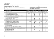
Fluke 123/124 Users Manual Unpacking the Test Tool Kit The following items are included in your test tool kit. (see Figure 1.): # Description 1 Fluke Test Tool 2 Rechargeable Battery Pack 3 Power Adapter/Battery Charger 4 Shielded Test Leads with Black Ground Leads 5 Test Lead Black (... 15 10:1 Voltage Probe Note When new, the rechargeable battery pack is not fully charged. Fluke 123 Model 123 NiCd 1x Fluke 123/S Model 123 NiCd 2x) • • • • • Fluke 124 Model 124 NiMH 1x • Fluke 124/S Model 124 NiMH 2x) • • 2 See Chapter 2.
Fluke 123/124 Users Manual Unpacking the Test Tool Kit The following items are included in your test tool kit. (see Figure 1.): # Description 1 Fluke Test Tool 2 Rechargeable Battery Pack 3 Power Adapter/Battery Charger 4 Shielded Test Leads with Black Ground Leads 5 Test Lead Black (... 15 10:1 Voltage Probe Note When new, the rechargeable battery pack is not fully charged. Fluke 123 Model 123 NiCd 1x Fluke 123/S Model 123 NiCd 2x) • • • • • Fluke 124 Model 124 NiMH 1x • Fluke 124/S Model 124 NiMH 2x) • • 2 See Chapter 2.
FE 123 & 124 Users Manual
Page 11
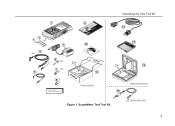
ScopeMeter Test Tool Kit 13 14 Fluke 123-S/124-S Fluke 124/124-S 3 1 9 Unpacking the Test Tool Kit 12 2 3 10 4 (2x) 6 (2x) 7 (3x) 5 11 8* Fluke 123/124 * Fluke 123/124 : 1x Fluke 123-S/124-S : 2x 15 Figure 1.
ScopeMeter Test Tool Kit 13 14 Fluke 123-S/124-S Fluke 124/124-S 3 1 9 Unpacking the Test Tool Kit 12 2 3 10 4 (2x) 6 (2x) 7 (3x) 5 11 8* Fluke 123/124 * Fluke 123/124 : 1x Fluke 123-S/124-S : 2x 15 Figure 1.
FE 123 & 124 Users Manual
Page 12
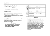
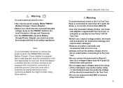
Fluke 123/124 Users Manual Safely Using the Test Tool Attention Carefully read the following safety information before using the test tool. Symbols used on the test tool ... pose hazard(s) to the user. To guarantee user safety, all signals should first be found throughout the manual. Warning To avoid electrical shock, use only Fluke power supply, Model PM8907 (Power Adapter/Battery Charger). 4 See explanation in manual Disposal information Equal potential inputs Earth Recycling information Double Insulation (Protection Class) Conformit...
Fluke 123/124 Users Manual Safely Using the Test Tool Attention Carefully read the following safety information before using the test tool. Symbols used on the test tool ... pose hazard(s) to the user. To guarantee user safety, all signals should first be found throughout the manual. Warning To avoid electrical shock, use only Fluke power supply, Model PM8907 (Power Adapter/Battery Charger). 4 See explanation in manual Disposal information Equal potential inputs Earth Recycling information Double Insulation (Protection Class) Conformit...
FE 123 & 124 Users Manual
Page 13
... more than 4800 VA: • Use only insulated voltage probes, test leads and adapters supplied with the Test Tool, or indicated as suitable for the Fluke 123/124 Test Tool. • Before use, inspect voltage probes, test leads and accessories for mechanical damage and replace when damaged. • Remove all probes, test leads...
... more than 4800 VA: • Use only insulated voltage probes, test leads and adapters supplied with the Test Tool, or indicated as suitable for the Fluke 123/124 Test Tool. • Before use, inspect voltage probes, test leads and accessories for mechanical damage and replace when damaged. • Remove all probes, test leads...
FE 123 & 124 Users Manual
Page 14
... A and B via BB120 300 V CAT III Input A and B via STL120 600 V CAT III Max. The matter should be turned off and disconnected from earth ground. Fluke 123/124 Users Manual • Do not insert metal objects into connectors. • Always use , inspect the test leads for mechanical damage and replace damaged test leads...
... A and B via BB120 300 V CAT III Input A and B via STL120 600 V CAT III Max. The matter should be turned off and disconnected from earth ground. Fluke 123/124 Users Manual • Do not insert metal objects into connectors. • Always use , inspect the test leads for mechanical damage and replace damaged test leads...
FE 123 & 124 Users Manual
Page 16
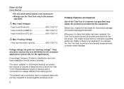
Fluke 123/124 Users Manual Resetting the Test Tool If you want to switch the cursors on , and you will see a screen that looks like Figure 1-2. Now look at the display; in Fluke 124 this key is used to restore the test tool settings as delivered from the factory, do the following: Turn the test tool off. Press and release. you should hear a double beep, indicating the Reset was successful. The test tool turns on . The F4 key of Fluke 123 is used to control the contrast; Release. The Screen After Reset 8 Press and hold. Fluke 123 Fluke 124 Figure 1-2.
Fluke 123/124 Users Manual Resetting the Test Tool If you want to switch the cursors on , and you will see a screen that looks like Figure 1-2. Now look at the display; in Fluke 124 this key is used to restore the test tool settings as delivered from the factory, do the following: Turn the test tool off. Press and release. you should hear a double beep, indicating the Reset was successful. The test tool turns on . The F4 key of Fluke 123 is used to control the contrast; Release. The Screen After Reset 8 Press and hold. Fluke 123 Fluke 124 Figure 1-2.
FE 123 & 124 Users Manual
Page 17
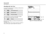
To change the brightness of the display in Fluke 123, do the following : Dim the backlight. The high brightness increases when you connect the power adapter. . 9 To save battery power, the screen has an economic ... display lengthens maximum battery power operation time. Select LIGHT Dim or brighten the backlight. Brighten the backlight again. 1 Using The Test Tool Changing Backlight In Fluke 124, do the following : Press to get access to the display functions.
To change the brightness of the display in Fluke 123, do the following : Dim the backlight. The high brightness increases when you connect the power adapter. . 9 To save battery power, the screen has an economic ... display lengthens maximum battery power operation time. Select LIGHT Dim or brighten the backlight. Brighten the backlight again. 1 Using The Test Tool Changing Backlight In Fluke 124, do the following : Press to get access to the display functions.
FE 123 & 124 Users Manual
Page 18
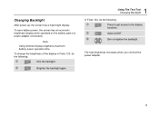
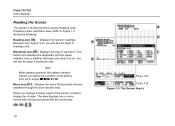
... input A readings only. Waveform area (B): Displays the input A waveform. The area displays one or more menus with choices accessed with the arrow keys: . 10 Fluke 123 Fluke 124 Figure 1-3. Fluke 123/124 Users Manual Reading the Screen The screen is on , you will see the input A waveform only. Because only input A is divided into three areas: Reading...
... input A readings only. Waveform area (B): Displays the input A waveform. The area displays one or more menus with choices accessed with the arrow keys: . 10 Fluke 123 Fluke 124 Figure 1-3. Fluke 123/124 Users Manual Reading the Screen The screen is on , you will see the input A waveform only. Because only input A is divided into three areas: Reading...

FE 123 & 124 Users Manual
Page 20
... measurements. Measurement Connections COM You can always use only one COM (common) connection, or ensure that all single input measurements possible with the red input A . Fluke 123/124 Users Manual Looking at the Measurement Connections Look at the same potential. 12 Figure 1-5.
... measurements. Measurement Connections COM You can always use only one COM (common) connection, or ensure that all single input measurements possible with the red input A . Fluke 123/124 Users Manual Looking at the Measurement Connections Look at the same potential. 12 Figure 1-5.
FE 123 & 124 Users Manual
Page 22
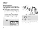
Measurement Setup Highlight Hz. Select Hz. The former main reading has now moved to be measured. Figure 1-7. Fluke 123/124 Users Manual Making Measurements The reading area displays the numeric readings of the chosen measurements on the waveform that Hz is applied to the input ...
Measurement Setup Highlight Hz. Select Hz. The former main reading has now moved to be measured. Figure 1-7. Fluke 123/124 Users Manual Making Measurements The reading area displays the numeric readings of the chosen measurements on the waveform that Hz is applied to the input ...

FE 123 & 124 Users Manual
Page 24
... hands-free measurements. Because no special keys accompany the Touch Hold function, you have a stable display. The screen continues to normal measurement. Measure the signal. Fluke 123/124 Users Manual Freezing the Screen You can use this function for the Touch Hold function: Open the INPUT A menu.
... hands-free measurements. Because no special keys accompany the Touch Hold function, you have a stable display. The screen continues to normal measurement. Measure the signal. Fluke 123/124 Users Manual Freezing the Screen You can use this function for the Touch Hold function: Open the INPUT A menu.
FE 123 & 124 Users Manual
Page 26
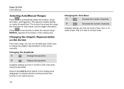
... to 500 V/div when using the test leads. Press a second time to 5 s/div in normal mode. Available settings are from 20 ns/div (Fluke 123) or 10 ns/div (Fluke 124) to select the manual range. MANUAL appears at the bottom of periods. Observe that the continuous Auto Set function is not valid anymore...
... to 500 V/div when using the test leads. Press a second time to 5 s/div in normal mode. Available settings are from 20 ns/div (Fluke 123) or 10 ns/div (Fluke 124) to select the manual range. MANUAL appears at the bottom of periods. Observe that the continuous Auto Set function is not valid anymore...