User Manual
Page 12
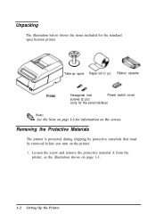
... the illustration shows on the printer. 1. Removing the Protective Materials The printer is protected during shipping by protective materials that must be removed before you turn on page 1-3. 1-2 Setting Up the Printer
... the illustration shows on the printer. 1. Removing the Protective Materials The printer is protected during shipping by protective materials that must be removed before you turn on page 1-3. 1-2 Setting Up the Printer
User Manual
Page 14
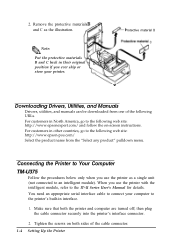
...Computer TM-U375 Follow the procedures below only when you use the printer with the intelligent module, refer to the following web site: http://www.epson-pos.com/ Select the product name from one of the following web site: http://www.epsonexpert.com/ and follow the on both the printer ...and computer are turned off; Remove the protective materials and C as a single unit (not connected to the printer's built-in their original C position if you use the printer ...
...Computer TM-U375 Follow the procedures below only when you use the printer with the intelligent module, refer to the following web site: http://www.epson-pos.com/ Select the product name from one of the following web site: http://www.epsonexpert.com/ and follow the on both the printer ...and computer are turned off; Remove the protective materials and C as a single unit (not connected to the printer's built-in their original C position if you use the printer ...

User Manual
Page 15
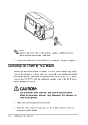
.... TM-U375P You need an appropriate parallel interface cable to connect your computer to use an interface cable that the printer and the computer are turned off. Setting Up the Printer 1-5 If you plan to the printer. 1. Notch (one or more lines) Inch-type Millimeter-type 3. Then plug the cable into...
.... TM-U375P You need an appropriate parallel interface cable to connect your computer to use an interface cable that the printer and the computer are turned off. Setting Up the Printer 1-5 If you plan to the printer. 1. Notch (one or more lines) Inch-type Millimeter-type 3. Then plug the cable into...
User Manual
Page 16
... the printer's drawer kick-out connector until they lock in place on both sides of the cable to an intelligent module). (Intelligent module connection is turned off. 2. Connecting the Printer to Your Drawer Follow the procedures below to connect a drawer to the IT-U Series User's Manual for details. Use a drawer that...
... the printer's drawer kick-out connector until they lock in place on both sides of the cable to an intelligent module). (Intelligent module connection is turned off. 2. Connecting the Printer to Your Drawer Follow the procedures below to connect a drawer to the IT-U Series User's Manual for details. Use a drawer that...
User Manual
Page 20
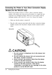
... not connect a telephone line to an intelligent module). Never connect any damage to the other than the display module to the DM connector, Seiko Epson Corporation is turned off. 2. Connecting the Printer to Your Direct Connection Display Module (For the TM-U375 only) Follow the procedures below to connect a direct connection display...
... not connect a telephone line to an intelligent module). Never connect any damage to the other than the display module to the DM connector, Seiko Epson Corporation is turned off. 2. Connecting the Printer to Your Direct Connection Display Module (For the TM-U375 only) Follow the procedures below to connect a direct connection display...
User Manual
Page 21
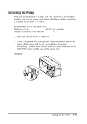
... (not connected to an intelligent module), you need to ground your printer. (Intelligent module connection is available for the TM-U375 only.) Recommended wire is turned off. 2. Connect the ground wire to connect the ground wire. Make sure that the printer is described below. TM-U375 Setting Up the Printer 1-11...
... (not connected to an intelligent module), you need to ground your printer. (Intelligent module connection is available for the TM-U375 only.) Recommended wire is turned off. 2. Connect the ground wire to connect the ground wire. Make sure that the printer is described below. TM-U375 Setting Up the Printer 1-11...
User Manual
Page 22
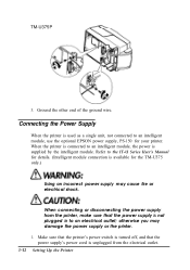
Refer to an intelligent module, use the optional EPSON power supply, PS-150 for the TM-U375 only.) Using an incorrect power supply may damage the power supply or the printer. 1. Connecting the Power ...-U375P 3. Ground the other end of the ground wire. When the printer is available for your printer. Make sure that the printer's power switch is turned off, and that the power supply is not plugged in to an intelligent module, the power is unplugged from the printer, make sure that the...
Refer to an intelligent module, use the optional EPSON power supply, PS-150 for the TM-U375 only.) Using an incorrect power supply may damage the power supply or the printer. 1. Connecting the Power ...-U375P 3. Ground the other end of the ground wire. When the printer is available for your printer. Make sure that the printer's power switch is turned off, and that the power supply is not plugged in to an intelligent module, the power is unplugged from the printer, make sure that the...

User Manual
Page 24
.... otherwise the ribbon cassette may be damaged. This is not receiving data when you replace a ribbon cassette; Turn on the cassette; Installing the Ribbon Cassette A CAUTIONS: Never turn the ribbon cassette's knob in the opposite direction of the arrow, to place the ribbon in the position as... the ribbon in the correct position. 1-14 Setting Up the Printer otherwise data may be lost. * Note: % Use the EPSON ERC-38 ribbon cassette for your printer. 1. Turn the ribbon cassette's knob two or three times in the direction of the arrow marked on the printer and open the printer...
.... otherwise the ribbon cassette may be damaged. This is not receiving data when you replace a ribbon cassette; Turn on the cassette; Installing the Ribbon Cassette A CAUTIONS: Never turn the ribbon cassette's knob in the opposite direction of the arrow, to place the ribbon in the position as... the ribbon in the correct position. 1-14 Setting Up the Printer otherwise data may be lost. * Note: % Use the EPSON ERC-38 ribbon cassette for your printer. 1. Turn the ribbon cassette's knob two or three times in the direction of the arrow marked on the printer and open the printer...

User Manual
Page 26
... below points towards the front of the printer. Note that matches the specifications. , Note: Q3 The printer must be turned on the printer, open the printer cover, and remove the take-up spool. 3. Turn on before installing the paper roll. 1. Installing the Paper Roll Use a paper roll that the arrow in the...
... below points towards the front of the printer. Note that matches the specifications. , Note: Q3 The printer must be turned on the printer, open the printer cover, and remove the take-up spool. 3. Turn on before installing the paper roll. 1. Installing the Paper Roll Use a paper roll that the arrow in the...
User Manual
Page 28
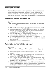
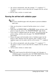
...after the self-test. 5. Running the self-test with the paper roll, slip paper, or validation paper. Make sure the printer is turned off and the printer cover is closed properly. 2. You can run the self test described below. The self-test prints the printer settings.../SLIP light flashes. 4. Continue to feed slip paper into the printer. The VALIDATION/SLIP light flashes. 3. While holding down the RELEASE button and turn on the paper. Feed a sheet of slip paper into the printer until the self-test prints "*** completed ***". 1-18 Setting Up the Printer Running...
...after the self-test. 5. Running the self-test with the paper roll, slip paper, or validation paper. Make sure the printer is turned off and the printer cover is closed properly. 2. You can run the self test described below. The self-test prints the printer settings.../SLIP light flashes. 4. Continue to feed slip paper into the printer. The VALIDATION/SLIP light flashes. 3. While holding down the RELEASE button and turn on the paper. Feed a sheet of slip paper into the printer until the self-test prints "*** completed ***". 1-18 Setting Up the Printer Running...
User Manual
Page 29
Self-test mode switches to prevent validation paper jams. 1. Make sure the printer is turned off and the printer cover is ready to receive data from the character table. The self-test prints the printer settings, and then ejects the ... paper , Note: Qa Be sure to install the paper roll in the printer to normal mode. Hold down the PAPER FEED and RELEASE buttons and turn on the printer to pause the self-test for the paper roll, slip paper, or validation paper at any point, press the PAPER FEED button...
Self-test mode switches to prevent validation paper jams. 1. Make sure the printer is turned off and the printer cover is ready to receive data from the character table. The self-test prints the printer settings, and then ejects the ... paper , Note: Qa Be sure to install the paper roll in the printer to normal mode. Hold down the PAPER FEED and RELEASE buttons and turn on the printer to pause the self-test for the paper roll, slip paper, or validation paper at any point, press the PAPER FEED button...

User Manual
Page 30
... sure the printer is marked on each set the DIP switches. There are in the second. 1-20 Setting Up the Printer Notice that ON is turned off. 2. Numbers starting with 1 are in the first set, and numbers starting with 2 are two sets of switches. Remove the screw from the DIP switch... column settings by changing the DIP switch settings. 1. Use the following tables to move the switches. 4. You can damage the printer. Setting the DIP Switches Turn off the DIP switch cover, as shown in the illustration below. 3. Use tweezers or another narrow tool to set of switches.
... sure the printer is marked on each set the DIP switches. There are in the second. 1-20 Setting Up the Printer Notice that ON is turned off. 2. Numbers starting with 1 are in the first set, and numbers starting with 2 are two sets of switches. Remove the screw from the DIP switch... column settings by changing the DIP switch settings. 1. Use the following tables to move the switches. 4. You can damage the printer. Setting the DIP Switches Turn off the DIP switch cover, as shown in the illustration below. 3. Use tweezers or another narrow tool to set of switches.
User Manual
Page 32
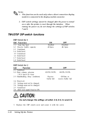
... not change the settings of switch 2-4, 2-5, 2-6 and 2-8. 5. * Notes: Qh 1. This function can be changed . 2-7 Undefined 2-8 nInit reset signal Fixed to the display module connector. 2. When turning the power on or after the printer is reset through the interface. Replace the DIP switch cover and secure it with the screw. 1-22 Setting.... 2-6 Settings must not be changed after the power is connected to ON. DIP switch settings cannot be used only when a direct connection display module is turned on , do not change the settings of DIP switches 7 and 8.
... not change the settings of switch 2-4, 2-5, 2-6 and 2-8. 5. * Notes: Qh 1. This function can be changed . 2-7 Undefined 2-8 nInit reset signal Fixed to the display module connector. 2. When turning the power on or after the printer is reset through the interface. Replace the DIP switch cover and secure it with the screw. 1-22 Setting.... 2-6 Settings must not be changed after the power is connected to ON. DIP switch settings cannot be used only when a direct connection display module is turned on , do not change the settings of DIP switches 7 and 8.

User Manual
Page 35
You can use the provided power switch cover to attach the cover. Setting Up the Printer 1-25 Attach the cover as shown in the illustration below. If an accident occurs when the power switch cover is attached, unplug the power supply cord from accidental or improper operation. Push to protect the power switch from the outlet immediately. Using the Power Switch Cover You can turn the power on or off with the switch cover attached by inserting a pointed object (like a ball point pen) through either of the two small holes on the switch cover.
You can use the provided power switch cover to attach the cover. Setting Up the Printer 1-25 Attach the cover as shown in the illustration below. If an accident occurs when the power switch cover is attached, unplug the power supply cord from accidental or improper operation. Push to protect the power switch from the outlet immediately. Using the Power Switch Cover You can turn the power on or off with the switch cover attached by inserting a pointed object (like a ball point pen) through either of the two small holes on the switch cover.
User Manual
Page 38
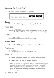
.... POWER (green) The POWER light is on when the printer power is the case. 2-2 Using the Printer The ERROR light goes off after you first turn on or is flashing when the printer is open. l When the printer stops printing because it senses the paper roll end.
.... POWER (green) The POWER light is on when the printer power is the case. 2-2 Using the Printer The ERROR light goes off after you first turn on or is flashing when the printer is open. l When the printer stops printing because it senses the paper roll end.

User Manual
Page 42
otherwise data may be lost. , Note: Qh Use the EPSON-ERC-38 ribbon cassette for your printer. 2-6 Using the Printer 2. Reinstall a new paper roll by following the steps in Installing the Paper Roll in the ... below . 3. Press the PAPER LOAD switch and remove the paper in the direction of the arrow marked on the cassette; Replacing the Ribbon Cassette Never turn the ribbon cassette's feed knob in Chapter 1.
otherwise data may be lost. , Note: Qh Use the EPSON-ERC-38 ribbon cassette for your printer. 2-6 Using the Printer 2. Reinstall a new paper roll by following the steps in Installing the Paper Roll in the ... below . 3. Press the PAPER LOAD switch and remove the paper in the direction of the arrow marked on the cassette; Replacing the Ribbon Cassette Never turn the ribbon cassette's feed knob in Chapter 1.
User Manual
Page 43
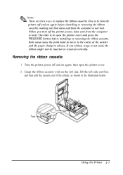
... button before installing or removing the ribbon cassette. One is to the center of the printer, as shown in the illustration below. Using the Printer 2-7 Turn the printer power off and on again before installing or removing the ribbon cassette, making sure that data sent from the computer is not lost... the ribbon might not be inserted or removed correctly. Both ways cause the print head to move to turn the printer off the printer power, data sent from the computer is lost . (When you turn off and on again; Tab- If one of these ways is to replace the ribbon cassette. Removing...
... button before installing or removing the ribbon cassette. One is to the center of the printer, as shown in the illustration below. Using the Printer 2-7 Turn the printer power off and on again before installing or removing the ribbon cassette, making sure that data sent from the computer is not lost... the ribbon might not be inserted or removed correctly. Both ways cause the print head to move to turn the printer off the printer power, data sent from the computer is lost . (When you turn off and on again; Tab- If one of these ways is to replace the ribbon cassette. Removing...

User Manual
Page 44
Then rotate the cassette's knob two or three more times. Installing the ribbon cassette 1. This is necessary to take up any slack in the ribbon. Turn the ribbon cassette's knob two or three times in the direction of the arrow, to place the ribbon in the position as shown below, and push the ribbon cassette into the printer until it clicks. or 3 times 2. Insert the ribbon in the correct position. 2-8 Using the Printer
Then rotate the cassette's knob two or three more times. Installing the ribbon cassette 1. This is necessary to take up any slack in the ribbon. Turn the ribbon cassette's knob two or three times in the direction of the arrow, to place the ribbon in the position as shown below, and push the ribbon cassette into the printer until it clicks. or 3 times 2. Insert the ribbon in the correct position. 2-8 Using the Printer
User Manual
Page 48
... is properly plugged into the printer's power connector. If the JOURNAL OUT light is nearly or completely depleted. The ERROR light is properly closed. First, turn off : Make sure that the power supply's DC cable is printed. Make sure that the power supply's power cord is on . Install a new paper roll...
... is properly plugged into the printer's power connector. If the JOURNAL OUT light is nearly or completely depleted. The ERROR light is properly closed. First, turn off : Make sure that the power supply's DC cable is printed. Make sure that the power supply's power cord is on . Install a new paper roll...
User Manual
Page 49
... has been printing for quite a while, the print head may be installed properly. The ERROR light is off but nothing is not overheated, turn off the printer and turn it is printing, but nothing is overheated, the printer will resume printing when the head has cooled (usually within two or three minutes...
... has been printing for quite a while, the print head may be installed properly. The ERROR light is off but nothing is not overheated, turn off the printer and turn it is printing, but nothing is overheated, the printer will resume printing when the head has cooled (usually within two or three minutes...