Installation Guide
Page 1
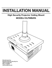
Brea, CA 92821 www.LocDown.com INSTALLATION MANUAL High Security Projector Ceiling Mount MODEL# ELPMBATA Manufactured by: Business Machine Security, Inc. 520 W. Central Ave.
Brea, CA 92821 www.LocDown.com INSTALLATION MANUAL High Security Projector Ceiling Mount MODEL# ELPMBATA Manufactured by: Business Machine Security, Inc. 520 W. Central Ave.
Installation Guide
Page 2
Table of Contents Limited Warranty Information 3 Contact Business Machine Security 3 Warning Statement...3 Parts List...4 Mount Assembly...5 Securing Receiver Tray to Pipe 6 Mounting Projector to Grid Plate 7-9 Locking Grid Plate to Receiver Tray 10 Adjusting Mount...11 INSTALLATION MANUAL 2
Table of Contents Limited Warranty Information 3 Contact Business Machine Security 3 Warning Statement...3 Parts List...4 Mount Assembly...5 Securing Receiver Tray to Pipe 6 Mounting Projector to Grid Plate 7-9 Locking Grid Plate to Receiver Tray 10 Adjusting Mount...11 INSTALLATION MANUAL 2
Installation Guide
Page 3
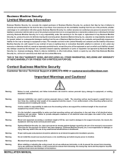
... combined total weight of its mounts for the repair or replacement of any warranty or otherwise shall not, except as expressly provided herein, exceed the price of all times throughout the installation process. Warning It is free and clear of the equipment or part on which it any purpose other goods. Contact Business Machine Security Customer Service/ Technical Support at all...
... combined total weight of its mounts for the repair or replacement of any warranty or otherwise shall not, except as expressly provided herein, exceed the price of all times throughout the installation process. Warning It is free and clear of the equipment or part on which it any purpose other goods. Contact Business Machine Security Customer Service/ Technical Support at all...
Installation Guide
Page 4
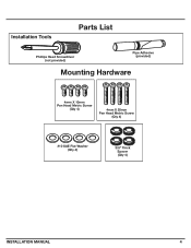
Installation Tools Parts List Phillips Head Screwdriver (not provided) Pipe Adhesive (provided) Mounting Hardware 4mm X 10mm Pan Head Metric Screw (Qty 4) 4mm X 20mm Pan Head Metric Screw (Qty 4) #10 SAE Flat Washer (Qty 4) 3/8" Thick Spacer (Qty 4) INSTALLATION MANUAL 4
Installation Tools Parts List Phillips Head Screwdriver (not provided) Pipe Adhesive (provided) Mounting Hardware 4mm X 10mm Pan Head Metric Screw (Qty 4) 4mm X 20mm Pan Head Metric Screw (Qty 4) #10 SAE Flat Washer (Qty 4) 3/8" Thick Spacer (Qty 4) INSTALLATION MANUAL 4
Installation Guide
Page 5
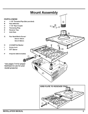
Mount Assembly PARTS LEGEND A 1-1/2" Threaded Pipe (Not provided) B Pipe Adhesive C 1-1/2" Pipe Coupler D Tensioning Ring E Receiver Tray F Grid Plate G Pan Head Metric Screw* 4mm X 10mm 4mm X 20mm H #10 SAE Flat Washer I Screw Lock J 3/8" Spacer P Projector (Not included) *see pages 7-9 for proper hardware to use for your model projector GRID PLATE TO RECEIVER TRAY INSTALLATION MANUAL 5
Mount Assembly PARTS LEGEND A 1-1/2" Threaded Pipe (Not provided) B Pipe Adhesive C 1-1/2" Pipe Coupler D Tensioning Ring E Receiver Tray F Grid Plate G Pan Head Metric Screw* 4mm X 10mm 4mm X 20mm H #10 SAE Flat Washer I Screw Lock J 3/8" Spacer P Projector (Not included) *see pages 7-9 for proper hardware to use for your model projector GRID PLATE TO RECEIVER TRAY INSTALLATION MANUAL 5
Installation Guide
Page 6
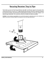
... (E) already assembled, onto the pre-installed 1-1/2" standard pipe threads (A). Screw the coupler (C) clockwise (as possible. Securing Receiver Tray to Pipe Twist off the tip. Apply it to which this mount will be as tight and stable as viewed from the Pipe Thread Adhesive tube (B). This connection should be attached, can support four times the combined weight of...
... (E) already assembled, onto the pre-installed 1-1/2" standard pipe threads (A). Screw the coupler (C) clockwise (as possible. Securing Receiver Tray to Pipe Twist off the tip. Apply it to which this mount will be as tight and stable as viewed from the Pipe Thread Adhesive tube (B). This connection should be attached, can support four times the combined weight of...
Installation Guide
Page 7
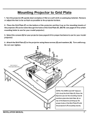
Remove or adjust the feet to be seen through the holes of the Grid Plate (F). (NOTE: see pages 8-9 for proper hardware to use for your model projector) 4. Turn until snug. Place the Spacers (J) over tighten. Select the screws (G) for your projector (see pages 8-9 for which mounting holes to use for your model projector) 3. Do not over the mounting inserts and then place the...
Remove or adjust the feet to be seen through the holes of the Grid Plate (F). (NOTE: see pages 8-9 for proper hardware to use for your model projector) 4. Turn until snug. Place the Spacers (J) over tighten. Select the screws (G) for your projector (see pages 8-9 for which mounting holes to use for your model projector) 3. Do not over the mounting inserts and then place the...

Installation Guide
Page 8
Epson Projector Model# 1700c, 1705c, 1710c, 1715c Epson Projector Model# S5, 77c, 83+, 822+, 400W Mounting Inserts HARDWARE Mounting Inserts: Grid Plate Alignment • #10 SAE Flat Washers (Qty 3) • 4mm X 10mm Pan Head Metric Screws (Qty 3) INSTALLATION MANUAL Mounting Inserts Grid Plate Alignment HARDWARE Mounting Inserts: • #10 SAE Flat Washers (Qty 3) • 4mm X 10mm Pan Head Metric Screws (Qty 3) • 4mm X 20mm Pan Head Metric Screws (Qty 3) (400W model only) • 3/8 Spacers (Qty 3) (400w model only) 8
Epson Projector Model# 1700c, 1705c, 1710c, 1715c Epson Projector Model# S5, 77c, 83+, 822+, 400W Mounting Inserts HARDWARE Mounting Inserts: Grid Plate Alignment • #10 SAE Flat Washers (Qty 3) • 4mm X 10mm Pan Head Metric Screws (Qty 3) INSTALLATION MANUAL Mounting Inserts Grid Plate Alignment HARDWARE Mounting Inserts: • #10 SAE Flat Washers (Qty 3) • 4mm X 10mm Pan Head Metric Screws (Qty 3) • 4mm X 20mm Pan Head Metric Screws (Qty 3) (400W model only) • 3/8 Spacers (Qty 3) (400w model only) 8
Installation Guide
Page 9
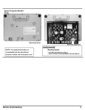
Epson Projector Model# 6110i Mounting Inserts NOTE: For updated information on compatibility with the latest Epson projector models, visit www.epson.com" Grid Plate Alignment HARDWARE Mounting Inserts: • #10 SAE Flat Washers (Qty 4) • 4mm X 10mm Pan Head Metric Screws (Qty 4) INSTALLATION MANUAL 9
Epson Projector Model# 6110i Mounting Inserts NOTE: For updated information on compatibility with the latest Epson projector models, visit www.epson.com" Grid Plate Alignment HARDWARE Mounting Inserts: • #10 SAE Flat Washers (Qty 4) • 4mm X 10mm Pan Head Metric Screws (Qty 4) INSTALLATION MANUAL 9
Installation Guide
Page 10
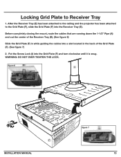
... figure 7 INSTALLATION MANUAL 10 Locking Grid Plate to the Grid Plate (F), slide the Grid Plate (F) into the Receiver Tray (E). Put the Screw Lock (I) into a slot located in while guiding the cables into the Grid Plate (F) and turn clockwise until it is snug. Before completely closing the mount, route the... cables that are running down the 1-1/2" Pipe (A) and out the center of the Receiver Tray (E). (See figure 6) Slide the Grid Plate (F) in the back of the Grid Plate (F). (See figure 7) 2. After the Receiver Tray (E) has been attached to the ceiling and the projector...
... figure 7 INSTALLATION MANUAL 10 Locking Grid Plate to the Grid Plate (F), slide the Grid Plate (F) into the Receiver Tray (E). Put the Screw Lock (I) into a slot located in while guiding the cables into the Grid Plate (F) and turn clockwise until it is snug. Before completely closing the mount, route the... cables that are running down the 1-1/2" Pipe (A) and out the center of the Receiver Tray (E). (See figure 6) Slide the Grid Plate (F) in the back of the Grid Plate (F). (See figure 7) 2. After the Receiver Tray (E) has been attached to the ceiling and the projector...
Installation Guide
Page 11
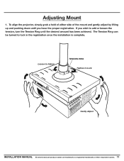
The Tension Ring can be turned to Lock Gently Adjust INSTALLATION MANUAL All other brand and product names are trademarks or registered trademarks of the mount and gently adjust by lifting up and pushing down until the desired amount has been achieved. Loosen to Adjust TENSION RING Tighten to lock in the registration once the installation is complete. If you wish to add or lessen the tension, turn the Tension Ring until you have the proper registration. Adjusting Mount 1. To align the projector, simply grab a hold of either side of their respected owners. 11
The Tension Ring can be turned to Lock Gently Adjust INSTALLATION MANUAL All other brand and product names are trademarks or registered trademarks of the mount and gently adjust by lifting up and pushing down until the desired amount has been achieved. Loosen to Adjust TENSION RING Tighten to lock in the registration once the installation is complete. If you wish to add or lessen the tension, turn the Tension Ring until you have the proper registration. Adjusting Mount 1. To align the projector, simply grab a hold of either side of their respected owners. 11
