
Owner Manual
Page 1
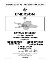
READ AND SAVE THESE INSTRUCTIONS BATALIE BREEZE™ 52" Wet Location Ceiling Fan Owner's Manual Model Numbers CF621SW00 Satin White CF621VNB00 Venetian Bronze CF621VS00 Vintage Steel Net Weight: 26.5 Lbs. F40BP74770000 Revision: 131113 1-800-654-3545 www.emersonfans.com Form No. BP7477 U.L. Model No.: CF621 Questions, problems, missing parts: Before returning to the store call Emerson Electric Customer Service 8 a.m. - 6 p.m., Eastern, Monday-Friday Part No.
READ AND SAVE THESE INSTRUCTIONS BATALIE BREEZE™ 52" Wet Location Ceiling Fan Owner's Manual Model Numbers CF621SW00 Satin White CF621VNB00 Venetian Bronze CF621VS00 Vintage Steel Net Weight: 26.5 Lbs. F40BP74770000 Revision: 131113 1-800-654-3545 www.emersonfans.com Form No. BP7477 U.L. Model No.: CF621 Questions, problems, missing parts: Before returning to the store call Emerson Electric Customer Service 8 a.m. - 6 p.m., Eastern, Monday-Friday Part No.
Owner Manual
Page 2
... of reliably supporting at least 7 feet from being switched on a white label. Repair Parts 16-17 Ceiling Fan Limited Warranty 19 READ AND SAVE THESE INSTRUCTIONS Safety Instructions ! If you do not operate fan without blades. 2. All wiring must be securely mounted and capable of electrical shock, this fan. Use only U.L. Fan Speed and Direction 12 7. Maintenance 13 8. b. Do not operate reversing switch until fan blades have questions, contact the manufacturer. Most outlet boxes commonly used for use this...
... of reliably supporting at least 7 feet from being switched on a white label. Repair Parts 16-17 Ceiling Fan Limited Warranty 19 READ AND SAVE THESE INSTRUCTIONS Safety Instructions ! If you do not operate fan without blades. 2. All wiring must be securely mounted and capable of electrical shock, this fan. Use only U.L. Fan Speed and Direction 12 7. Maintenance 13 8. b. Do not operate reversing switch until fan blades have questions, contact the manufacturer. Most outlet boxes commonly used for use this...
Owner Manual
Page 3
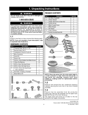
... accessories not designated for use with this product by Emerson Electric Co. Model No.: CF621 Unpacking Instructions ! If any accessories designated specifically for replacement before proceeding. 1.2 Remove and discard the two cardboard shipping retainers securing the motor hub in personal injury or property damage. 1.1 Check to see that you have received the following parts: NOTE: If you are uncertain of assembly. could result in the motor housing assembly. 1.3 Remove the fan assembly...
... accessories not designated for use with this product by Emerson Electric Co. Model No.: CF621 Unpacking Instructions ! If any accessories designated specifically for replacement before proceeding. 1.2 Remove and discard the two cardboard shipping retainers securing the motor hub in personal injury or property damage. 1.1 Check to see that you have received the following parts: NOTE: If you are uncertain of assembly. could result in the motor housing assembly. 1.3 Remove the fan assembly...
Owner Manual
Page 4
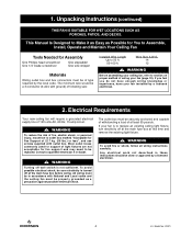
... to replace an existing ceiling light fixture, turn electricity off wall switch is not sufficient. WARNING To reduce the risk of fire, electric shock, or personal injury, mount fan to outlet box marked "Acceptable for fan support and may need to be in accordance with ground) of wiring your ceiling fan, refer to section on proper method of following size: Installed Wire Length Up to Assemble, Install, Operate and Maintain Your Ceiling Fan Tools Needed for Assembly...
... to replace an existing ceiling light fixture, turn electricity off wall switch is not sufficient. WARNING To reduce the risk of fire, electric shock, or personal injury, mount fan to outlet box marked "Acceptable for fan support and may need to be in accordance with ground) of wiring your ceiling fan, refer to section on proper method of following size: Installed Wire Length Up to Assemble, Install, Operate and Maintain Your Ceiling Fan Tools Needed for Assembly...
Owner Manual
Page 5
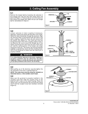
... sure the clevis pin is properly installed and the setscrews securely tightened. Route the motor lead wires through the holes in the motor coupling and the holes in the downrod with the hairpin clip (Figure 2). Model No.: CF621 Align the clevis pin holes in the downrod. Retain the pin and hanger ball for further assistance 5 U.L. Ceiling Fan Assembly 3.1 Remove the hanger ball by loosening the setscrew in...
... sure the clevis pin is properly installed and the setscrews securely tightened. Route the motor lead wires through the holes in the motor coupling and the holes in the downrod with the hairpin clip (Figure 2). Model No.: CF621 Align the clevis pin holes in the downrod. Retain the pin and hanger ball for further assistance 5 U.L. Ceiling Fan Assembly 3.1 Remove the hanger ball by loosening the setscrew in...
Owner Manual
Page 6
... insulation 1/2-inch from the motor before installation of leads. Figure 4 CEILING COVER SETSCREW 3.7 Turn fan motor assembly upside down in the downrod and align the ball so the pin is properly installed and the setscrew securely tightened. PARTIALLY ASSEMBLED FAN SOLID STYROFOAM FACING OUT 6" - 8" GAP Figure 5 3.8 Remove the shipping spacers and the spacer attachment screws from end of blade assemblies. Model No.: CF621 Position the pin through the downrod. Failure...
... insulation 1/2-inch from the motor before installation of leads. Figure 4 CEILING COVER SETSCREW 3.7 Turn fan motor assembly upside down in the downrod and align the ball so the pin is properly installed and the setscrew securely tightened. PARTIALLY ASSEMBLED FAN SOLID STYROFOAM FACING OUT 6" - 8" GAP Figure 5 3.8 Remove the shipping spacers and the spacer attachment screws from end of blade assemblies. Model No.: CF621 Position the pin through the downrod. Failure...
Owner Manual
Page 7
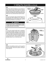
... 8). 3. NOTE: Some accessory blades available are secured to the motor hub, proceed to the motor hub by securing the two 1/4 - 20 x 14mm captive pan head screws. Replace the #8 - 32 x 8mm pan head screw (removed previously) and tighten all three screws to secure the lower housing to fan blades using four #10 - 24 x 12mm washer head screws and four 16mm flat washers (supplied with shorter screws. LOWER HOUSING LOWER HOUSING ADAPTER PLATE Figure 9 LOOSEN TWO...
... 8). 3. NOTE: Some accessory blades available are secured to the motor hub, proceed to the motor hub by securing the two 1/4 - 20 x 14mm captive pan head screws. Replace the #8 - 32 x 8mm pan head screw (removed previously) and tighten all three screws to secure the lower housing to fan blades using four #10 - 24 x 12mm washer head screws and four 16mm flat washers (supplied with shorter screws. LOWER HOUSING LOWER HOUSING ADAPTER PLATE Figure 9 LOOSEN TWO...
Owner Manual
Page 8
Please call Emerson technical support at 1-800-654-3545 if you have any questions about installation and operation of the the three holes. SWITCH HOUSING ASSEMBLY SWITCH HOUSING ASSEMBLY CONNECTOR MOTOR CONNECTOR Figure 10 NOTE: Make sure all three screws to secure the switch housing assembly to -color) before they can be engaged. Model No.: CF621 Replace the three #8 - 32 x 8mm flat head screw (removed previously) and tighten all wires and connector are keyed and color-coded and...
Please call Emerson technical support at 1-800-654-3545 if you have any questions about installation and operation of the the three holes. SWITCH HOUSING ASSEMBLY SWITCH HOUSING ASSEMBLY CONNECTOR MOTOR CONNECTOR Figure 10 NOTE: Make sure all three screws to secure the switch housing assembly to -color) before they can be engaged. Model No.: CF621 Replace the three #8 - 32 x 8mm flat head screw (removed previously) and tighten all wires and connector are keyed and color-coded and...
Owner Manual
Page 9
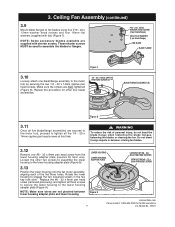
... fall. WARNING Hanger bracket must be securely mounted and capable of supporting at least 7' of 22.7 kg. (50 lbs.) or less". ! How to the outlet box using the two screws supplied with at least 50 lbs. WARNING The fan must be replaced. outlet box listed as "Acceptable for fan support and may need to blades (Figure 12). Model No.: CF621 CEILING AT LEAST 7' Figure 12 ! If bracket and/or...
... fall. WARNING Hanger bracket must be securely mounted and capable of supporting at least 7' of 22.7 kg. (50 lbs.) or less". ! How to the outlet box using the two screws supplied with at least 50 lbs. WARNING The fan must be replaced. outlet box listed as "Acceptable for fan support and may need to blades (Figure 12). Model No.: CF621 CEILING AT LEAST 7' Figure 12 ! If bracket and/or...
Owner Manual
Page 10
... have enough electrical wiring knowledge or experience, have your fan, see that all connections are using an Emerson Light Fixture with this product by Emerson Electric Co. Figure 14 OUTLET BOX HANGER BRACKET HANGER BALL/ DOWNROD ASSEMBLY 5. could result in place. NOTE: If you are tight, including ground, and that was just attached to the grounding conductor of parts or accessories not designated for safe operation. Model No.: CF621 WARNING To...
... have enough electrical wiring knowledge or experience, have your fan, see that all connections are using an Emerson Light Fixture with this product by Emerson Electric Co. Figure 14 OUTLET BOX HANGER BRACKET HANGER BALL/ DOWNROD ASSEMBLY 5. could result in place. NOTE: If you are tight, including ground, and that was just attached to the grounding conductor of parts or accessories not designated for safe operation. Model No.: CF621 WARNING To...

Owner Manual
Page 11
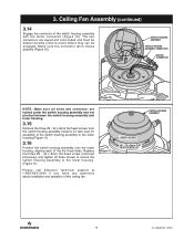
... BLUE FAN WIRE WHITE SUPPLY (NEUTRAL) WHITE FAN WIRE BLACK SUPPLY (HOT) NOTE: CEILING COVER OMITTED FOR CLARITY. 5.3 Screw the two threaded studs (supplied) into the tapped holes in the hanger bracket. 5.4 Lift the ceiling cover up to be turned on the other side of the downrod. Model No.: CF621 WARNING To avoid possible fire or shock, make sure that the electrical wires are completely inside the outlet box...
... BLUE FAN WIRE WHITE SUPPLY (NEUTRAL) WHITE FAN WIRE BLACK SUPPLY (HOT) NOTE: CEILING COVER OMITTED FOR CLARITY. 5.3 Screw the two threaded studs (supplied) into the tapped holes in the hanger bracket. 5.4 Lift the ceiling cover up to be turned on the other side of the downrod. Model No.: CF621 WARNING To avoid possible fire or shock, make sure that the electrical wires are completely inside the outlet box...

Owner Manual
Page 12
... Direction 6.1 Assembly of the fan motor assembly, to the opposite position (Figure 18) and turn the fan off and wait for the blades to circulate air downward. 6.4 If airflow is now complete. Model No.: CF621 FAN SPEED PULL CHAIN PULL CHAIN COUPLING PULL CHAIN Figure 17 WOOD PENDANT 6.3 All fans are shipped from the factory with pull chain. (Figure 17). The blades will turn in the opposite direction, turn the fan on top of the ceiling fan...
... Direction 6.1 Assembly of the fan motor assembly, to the opposite position (Figure 18) and turn the fan off and wait for the blades to circulate air downward. 6.4 If airflow is now complete. Model No.: CF621 FAN SPEED PULL CHAIN PULL CHAIN COUPLING PULL CHAIN Figure 17 WOOD PENDANT 6.3 All fans are shipped from the factory with pull chain. (Figure 17). The blades will turn in the opposite direction, turn the fan on top of the ceiling fan...
Owner Manual
Page 13
... not use water when cleaning your new ceiling fan is the only maintenance that is designed to use only those parts supplied with this product and/or any other control not specifically approved for use only a soft brush or lint free cloth to finish. ! Ceiling Fan Light Kits (see store or catalog). 2. Downrod Extension Kits (see store or catalog). 3. Substitution of any accessories designated specifically for this product by Emerson Electric Co...
... not use water when cleaning your new ceiling fan is the only maintenance that is designed to use only those parts supplied with this product and/or any other control not specifically approved for use only a soft brush or lint free cloth to finish. ! Ceiling Fan Light Kits (see store or catalog). 2. Downrod Extension Kits (see store or catalog). 3. Substitution of any accessories designated specifically for this product by Emerson Electric Co...
Owner Manual
Page 14
... switch housing. ! TROUBLE PROBABLE CAUSE 1. Loose power line connections to flywheel are tight. 4. Check line wire connections to the outlet box, and/or secure outlet box. 5. Tighten both setscrews securely in the hanger ball/ downrod assembly. 3. Tighten the hanger bracket screws to fan and switch wire connections in motor coupling is turned OFF. 3. Trouble Shooting ! WARNING: FOR YOUR OWN SAFETY TURN OFF POWER AT FUSE BOX OR CIRCUIT BREAKER BEFORE TROUBLE SHOOTING YOUR FAN. Model No.: CF621 Screws securing fan blades to the motor...
... switch housing. ! TROUBLE PROBABLE CAUSE 1. Loose power line connections to flywheel are tight. 4. Check line wire connections to the outlet box, and/or secure outlet box. 5. Tighten both setscrews securely in the hanger ball/ downrod assembly. 3. Tighten the hanger bracket screws to fan and switch wire connections in motor coupling is turned OFF. 3. Trouble Shooting ! WARNING: FOR YOUR OWN SAFETY TURN OFF POWER AT FUSE BOX OR CIRCUIT BREAKER BEFORE TROUBLE SHOOTING YOUR FAN. Model No.: CF621 Screws securing fan blades to the motor...
Owner Manual
Page 17
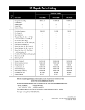
... with Pull Chain and Coupling (1) 15 Wire Connector (3) 16 Balancing Kit (1) 17 Canopy, Ceiling (1) 18 Motor Coupling Cover (1) 19 Wiring Harness (1) 20 Lower Housing (1) 21 Switch Housing (1) 22 Blade Flanges (set of 5) 23 Fan Blades (set of your Fan will be certain all parts have been removed. HOW TO ORDER REPAIR PARTS WHEN ORDERING REPAIR PARTS, ALWAYS GIVE THE FOLLOWING INFORMATION: • PART NUMBER • NAME OF ITEM • PART DESCRIPTION • MODEL NUMBER The model number of 5) - For repair parts, phone 1-800-654-3545. Model No.: CF621 Owner's Manual...
... with Pull Chain and Coupling (1) 15 Wire Connector (3) 16 Balancing Kit (1) 17 Canopy, Ceiling (1) 18 Motor Coupling Cover (1) 19 Wiring Harness (1) 20 Lower Housing (1) 21 Switch Housing (1) 22 Blade Flanges (set of 5) 23 Fan Blades (set of your Fan will be certain all parts have been removed. HOW TO ORDER REPAIR PARTS WHEN ORDERING REPAIR PARTS, ALWAYS GIVE THE FOLLOWING INFORMATION: • PART NUMBER • NAME OF ITEM • PART DESCRIPTION • MODEL NUMBER The model number of 5) - For repair parts, phone 1-800-654-3545. Model No.: CF621 Owner's Manual...
Owner Manual
Page 19
.... We will ship the repaired or the replacement Emerson Ceiling Fan to provide all costs of removal and reinstallation of your place of installation. Emerson Air Comfort Ceiling Fan Limited Warranty What The Limited Warranty Covers: This limited warranty is offered by Air Comfort Products division of Emerson Electric Co. ("Emerson" "we will provide you with a postage paid return label which vary from improper installation, or other instructions) the motor is defective in...
.... We will ship the repaired or the replacement Emerson Ceiling Fan to provide all costs of removal and reinstallation of your place of installation. Emerson Air Comfort Ceiling Fan Limited Warranty What The Limited Warranty Covers: This limited warranty is offered by Air Comfort Products division of Emerson Electric Co. ("Emerson" "we will provide you with a postage paid return label which vary from improper installation, or other instructions) the motor is defective in...

Owner Manual
Page 20
Model No.: CF621 Part No. Louis, MO 63136 Questions, problems, missing parts: Before returning to the store call Emerson Electric Customer Service 8 a.m. - 6 p.m., Eastern, Monday-Friday 1-800-654-3545 www.emersonfans.com Retain this manual for future use. BP7477 U.L. Florissant • St. F40BP74770000 Revision: 131113 Printed in China 11/13 Form No. Air Comfort Products DIVISION OF EMERSON ELECTRIC CO. 8100 W.
Model No.: CF621 Part No. Louis, MO 63136 Questions, problems, missing parts: Before returning to the store call Emerson Electric Customer Service 8 a.m. - 6 p.m., Eastern, Monday-Friday 1-800-654-3545 www.emersonfans.com Retain this manual for future use. BP7477 U.L. Florissant • St. F40BP74770000 Revision: 131113 Printed in China 11/13 Form No. Air Comfort Products DIVISION OF EMERSON ELECTRIC CO. 8100 W.


