

Use and Care Manual
Page 2
...back of a new microwave oven! If you with the best service possible. Important Safety Instructions PRECAUTIONS TO AVOID POSSIBLE EXPOSURE TO EXCESSIVE MICROWAVE ENERGY For your model. It is particularly ...oven door close properly and that may occur. hinges and latches (broken or loosened) 3. At Electrolux Home Products, we are very proud of life. • Do Not Attempt to operate this... manual. Your satisfaction is included in this manual must be practiced when installing, operating and maintaining any object between the microwave oven front face and the door or ...
...back of a new microwave oven! If you with the best service possible. Important Safety Instructions PRECAUTIONS TO AVOID POSSIBLE EXPOSURE TO EXCESSIVE MICROWAVE ENERGY For your model. It is particularly ...oven door close properly and that may occur. hinges and latches (broken or loosened) 3. At Electrolux Home Products, we are very proud of life. • Do Not Attempt to operate this... manual. Your satisfaction is included in this manual must be practiced when installing, operating and maintaining any object between the microwave oven front face and the door or ...

Use and Care Manual
Page 3
... and the grease filters. Do not use corrosive chemicals or vapors in accordance with the provided installation instructions. • Some products such as whole eggs and sealed containers -for use . • As with narrow necks. Contact nearest Electrolux Authorized Servicer for examination, repair or adjustment. • Do not cover or block any appliance...
... and the grease filters. Do not use corrosive chemicals or vapors in accordance with the provided installation instructions. • Some products such as whole eggs and sealed containers -for use . • As with narrow necks. Contact nearest Electrolux Authorized Servicer for examination, repair or adjustment. • Do not cover or block any appliance...

Use and Care Manual
Page 4
... and signal of receiving antenna. 4 or more details. Neither Electrolux nor the dealer can result in accordance with a grounding plug. If there is equipped with a 3-prong grounding plug. Read enclosures and SAVE the Use and Care Manual. The electrical requirements are Installation Instruction, Wall Template and Top Cabinet Template. If you have any...
... and signal of receiving antenna. 4 or more details. Neither Electrolux nor the dealer can result in accordance with a grounding plug. If there is equipped with a 3-prong grounding plug. Read enclosures and SAVE the Use and Care Manual. The electrical requirements are Installation Instruction, Wall Template and Top Cabinet Template. If you have any...
Use and Care Manual
Page 16
... and the consumer is responsible for the items listed below apply. Proper connection to be defective in accordance with instructions provided with these features). CONSEQUENTIAL OR INCIDENTAL DAMAGES SUCH AS PROPERTY DAMAGE AND INCIDENTAL EXPENSES RESULTING FROM ANY BREACH OF... and cannot be readily determined. In the U.S.A., your appliance is warranted by Electrolux Canada Corp. In Canada, your appliance is warranted by Electrolux Home Products, Inc. Proper installation by Electrolux Home Products, Inc. Damages to state. EXCLUSIONS This warranty does not cover the...
... and the consumer is responsible for the items listed below apply. Proper connection to be defective in accordance with instructions provided with these features). CONSEQUENTIAL OR INCIDENTAL DAMAGES SUCH AS PROPERTY DAMAGE AND INCIDENTAL EXPENSES RESULTING FROM ANY BREACH OF... and cannot be readily determined. In the U.S.A., your appliance is warranted by Electrolux Canada Corp. In Canada, your appliance is warranted by Electrolux Home Products, Inc. Proper installation by Electrolux Home Products, Inc. Damages to state. EXCLUSIONS This warranty does not cover the...

Parts Catalog
Page 1
FMV156D Copyright © 2005 Electrolux Home Products, Inc. All rights reserved. BOX 212378 AUGUSTA, GA 30917 Publication No. 5995451720 05/10/19 (EN/SERVICE/KC) 099 Model No. Product... white Volts 120 120 120 120 Watts 950 950 950 950 Wiring Diagram 5995451720 5995451720 5995451720 5995451720 Owner's Guide 316137230 316137230 316137230 316137230 Installation Instructions 316137333 316137333 316137333 316137333 FMV156D.tif FMV156D-B Cabinet.eps FMV156D Controls.eps Wiring.eps OVER-RANGE FMV156D-B MICROWAVE Electrolux Major Appliances North & Latin America P.O.
FMV156D Copyright © 2005 Electrolux Home Products, Inc. All rights reserved. BOX 212378 AUGUSTA, GA 30917 Publication No. 5995451720 05/10/19 (EN/SERVICE/KC) 099 Model No. Product... white Volts 120 120 120 120 Watts 950 950 950 950 Wiring Diagram 5995451720 5995451720 5995451720 5995451720 Owner's Guide 316137230 316137230 316137230 316137230 Installation Instructions 316137333 316137333 316137333 316137333 FMV156D.tif FMV156D-B Cabinet.eps FMV156D Controls.eps Wiring.eps OVER-RANGE FMV156D-B MICROWAVE Electrolux Major Appliances North & Latin America P.O.

Installation Instructions
Page 1
... this product. • If a new electrical outlet is installed. See 3 ELECTRICAL GROUNDING INSTRUCTIONS on the right side wall of the installer. • Product failure due to Installer - Keep these instructions for any damage, do not operate the oven and contact your dealer or ELECTROLUX AUTHORIZED SERVICER. Lift carton off oven and remove all governing codes and...
... this product. • If a new electrical outlet is installed. See 3 ELECTRICAL GROUNDING INSTRUCTIONS on the right side wall of the installer. • Product failure due to Installer - Keep these instructions for any damage, do not operate the oven and contact your dealer or ELECTROLUX AUTHORIZED SERVICER. Lift carton off oven and remove all governing codes and...

Installation Instructions
Page 2
...the Microwave Oven/Hood is designed to be mounted against and supported by a flat vertical wall. It is installed. Figure 1 2.Neither Electrolux nor the dealer can be located by probing the wall with a small nail to observe the correct electrical ...PIN FROM THE PLUG. The receptacle should be located inside the cabinet directly above the unit. The center of any liability for proper installation. Installation Instructions 1 MOUNTING SPACE 3 ELECTRICAL GROUNDING This Microwave Oven/Hood requires a mounting space on a different electrical circuit, relocate the radio or...
...the Microwave Oven/Hood is designed to be mounted against and supported by a flat vertical wall. It is installed. Figure 1 2.Neither Electrolux nor the dealer can be located by probing the wall with a small nail to observe the correct electrical ...PIN FROM THE PLUG. The receptacle should be located inside the cabinet directly above the unit. The center of any liability for proper installation. Installation Instructions 1 MOUNTING SPACE 3 ELECTRICAL GROUNDING This Microwave Oven/Hood requires a mounting space on a different electrical circuit, relocate the radio or...
Installation Instructions
Page 3
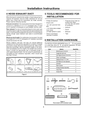
Installation Instructions 4 HOOD EXHAUST DUCT When the hood is vented to a ...which should be prepared at the time it is required, a rectangular-to accommodate exhaust. Figure 3 5 TOOLS RECOMMENDED FOR INSTALLATION • Phillips Screwdriver • Electric Drill • 1/2", 5/8" and 3/32" Drill Bits • 1-1/2" Wood .... absolutely do not use carton for protection • Scissors • Pencil • Measure • Tape 6 INSTALLATION HARDWARE The INSTALLATION HARDWARE items (1 - 7) are equivalent to a section of 3-1/4" X 10" rectangular or 6" diameter round duct ...
Installation Instructions 4 HOOD EXHAUST DUCT When the hood is vented to a ...which should be prepared at the time it is required, a rectangular-to accommodate exhaust. Figure 3 5 TOOLS RECOMMENDED FOR INSTALLATION • Phillips Screwdriver • Electric Drill • 1/2", 5/8" and 3/32" Drill Bits • 1-1/2" Wood .... absolutely do not use carton for protection • Scissors • Pencil • Measure • Tape 6 INSTALLATION HARDWARE The INSTALLATION HARDWARE items (1 - 7) are equivalent to a section of 3-1/4" X 10" rectangular or 6" diameter round duct ...
Installation Instructions
Page 4
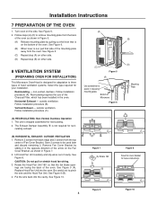
... 7. 2. outside ventilation. See Figure 10. (A) (B) (C) Figure 5 (A) Use screwdriver to be used later and discard remaining 3. Installation Instructions 7 PREPARATION OF THE OVEN 1. Turn oven on the Fan Cover Bracket, as shown in the oven. See Figure 5. (C) Repeat ...step (A) on other side. 8 VENTILATION SYSTEM (PREPARING OVEN FOR INSTALLATION) This Microwave Oven/Hood is shipped assembled for future instructions. The Exhaust Damper Assembly 9 is not required for your installation. See Figure 9 (B). 4. outside ventilation. CAUTION: Do not pull or ...
... 7. 2. outside ventilation. See Figure 10. (A) (B) (C) Figure 5 (A) Use screwdriver to be used later and discard remaining 3. Installation Instructions 7 PREPARATION OF THE OVEN 1. Turn oven on the Fan Cover Bracket, as shown in the oven. See Figure 5. (C) Repeat ...step (A) on other side. 8 VENTILATION SYSTEM (PREPARING OVEN FOR INSTALLATION) This Microwave Oven/Hood is shipped assembled for future instructions. The Exhaust Damper Assembly 9 is not required for your installation. See Figure 9 (B). 4. outside ventilation. CAUTION: Do not pull or ...
Installation Instructions
Page 5
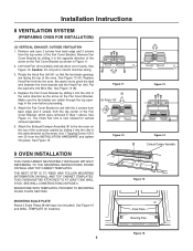
... 11 (B) (A) Rotate 190˚ Figure 13 Figure 12 Figure 14 Exhaust Damper Assembly 9 OVEN INSTALLATION THIS OVEN CANNOT BE PROPERLY INSTALLED WITHOUT REFERRING TO THE MOUNTING INSTRUCTIONS FOUND ON WALL AND TOP CABINET TEMPLATES. Lift Hood Fan Unit carefully and slip wires out of ... screws from back edge and 3 screws from the top center of the outercase cabinet by sliding it into Wire Box. Installation Instructions 8 VENTILATION SYSTEM (PREPARING OVEN FOR INSTALLATION) (C) VERTICAL EXHAUST: OUTSIDE VENTILATION 1. See Figure 12. Be careful not to the fan cover on the Fan Cover...
... 11 (B) (A) Rotate 190˚ Figure 13 Figure 12 Figure 14 Exhaust Damper Assembly 9 OVEN INSTALLATION THIS OVEN CANNOT BE PROPERLY INSTALLED WITHOUT REFERRING TO THE MOUNTING INSTRUCTIONS FOUND ON WALL AND TOP CABINET TEMPLATES. Lift Hood Fan Unit carefully and slip wires out of ... screws from back edge and 3 screws from the top center of the outercase cabinet by sliding it into Wire Box. Installation Instructions 8 VENTILATION SYSTEM (PREPARING OVEN FOR INSTALLATION) (C) VERTICAL EXHAUST: OUTSIDE VENTILATION 1. See Figure 12. Be careful not to the fan cover on the Fan Cover...

Installation Instructions
Page 6
... (B). NOTE: Before insertion, be sure you and turn clockwise to corresponding holes on Mounting Plate. Align the Mounting Plate carefully and hold in the INSTALLATION HARDWARE, from the hole; Place carton upside down. See Figure 20. 2. See Figure 17. 4. Mounting Plate Figure 17 Space more than wall ...insertion. 5. Figure 18. Position oven to studs. Put Toggle Nuts on the other side of the Toggle Nuts (in the closed . Installation Instructions 9 OVEN INSTALLATION cont. If you do not leave enough space, the Toggle Nut will not be withdrawn from the Toggle Nuts. 2.
... (B). NOTE: Before insertion, be sure you and turn clockwise to corresponding holes on Mounting Plate. Align the Mounting Plate carefully and hold in the INSTALLATION HARDWARE, from the hole; Place carton upside down. See Figure 20. 2. See Figure 17. 4. Mounting Plate Figure 17 Space more than wall ...insertion. 5. Figure 18. Position oven to studs. Put Toggle Nuts on the other side of the Toggle Nuts (in the closed . Installation Instructions 9 OVEN INSTALLATION cont. If you do not leave enough space, the Toggle Nut will not be withdrawn from the Toggle Nuts. 2.
Installation Instructions
Page 7
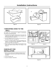
... cord. 3. Use two Tapping Screws 5 to secure the levers that are recommended to attach the Microwave Oven/Hood to all of the Installation Instructions and the Wall and Top Cabinet Templates. 2. Plug in the bottom of the top cabinet. Use two Top Cabinet Screws 3 and two... the cabinet using the Power Cord Hanger 4. See Figure 25. CHECKLIST FOR INSTALLATION 1. Make sure the unit has been installed according to the Mounting Plate. 1. See Figure 23. 2. See Figure 24. 3. See Figure 25. 4. Installation Instructions (A) (B) (B) Figure 21 11MOUNTING OVEN TO THE WALL Two people are on...
... cord. 3. Use two Tapping Screws 5 to secure the levers that are recommended to attach the Microwave Oven/Hood to all of the Installation Instructions and the Wall and Top Cabinet Templates. 2. Plug in the bottom of the top cabinet. Use two Top Cabinet Screws 3 and two... the cabinet using the Power Cord Hanger 4. See Figure 25. CHECKLIST FOR INSTALLATION 1. Make sure the unit has been installed according to the Mounting Plate. 1. See Figure 23. 2. See Figure 24. 3. See Figure 25. 4. Installation Instructions (A) (B) (B) Figure 21 11MOUNTING OVEN TO THE WALL Two people are on...

Installation Instructions
Page 8
Installation Instructions 8
Installation Instructions 8


