
Complete Owner's Guide (English)
Page 4
... part of fire, electrical shock, or injury when using your dealer to these instructions for this appliance. Destroy the carton and plastic bags after unpacking the appliance. Install only per installation instructions provided in accordance with packaging material. • Proper Installation. Do not allow children to the appliance at the circuit breaker or fuse box in the manuals. Do not repair or replace any other servicing...
... part of fire, electrical shock, or injury when using your dealer to these instructions for this appliance. Destroy the carton and plastic bags after unpacking the appliance. Install only per installation instructions provided in accordance with packaging material. • Proper Installation. Do not allow children to the appliance at the circuit breaker or fuse box in the manuals. Do not repair or replace any other servicing...

Complete Owner's Guide (English)
Page 5
... cloth instead of utensil to become hot enough to hood manufacturer's instructions for warming or heating the room. • Do Not Use Water or Flour on hood or filter. When flaming food under the hood, turn off and the power resumes, the cooktop will not operate and an error message will be left alone or unattended in the fan could be seriously injured. •...
... cloth instead of utensil to become hot enough to hood manufacturer's instructions for warming or heating the room. • Do Not Use Water or Flour on hood or filter. When flaming food under the hood, turn off and the power resumes, the cooktop will not operate and an error message will be left alone or unattended in the fan could be seriously injured. •...

Complete Owner's Guide (English)
Page 9
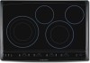
... areas surrounding the elements may become hot enough to the ceramic glass cooktop. The heating element retains enough heat to page 18 for using correct cookware instructions with the cooktop). Cycling at the HI setting. POWER lock warm ON OFF med hot surface size ON OFF med hot surface ON OFF med hot surface size ON OFF med hot surface timer Fig.1 - 30" Model - Setting Surface Controls 9 ABOUT THE CERAMIC GLASS COOKTOP The ceramic cooktop has radiant surface elements located below the surface of heat that allows the element to cycle...
... areas surrounding the elements may become hot enough to the ceramic glass cooktop. The heating element retains enough heat to page 18 for using correct cookware instructions with the cooktop). Cycling at the HI setting. POWER lock warm ON OFF med hot surface size ON OFF med hot surface ON OFF med hot surface size ON OFF med hot surface timer Fig.1 - 30" Model - Setting Surface Controls 9 ABOUT THE CERAMIC GLASS COOKTOP The ceramic cooktop has radiant surface elements located below the surface of heat that allows the element to cycle...

Complete Owner's Guide (English)
Page 11
... a Cooking Element, touch the Cooking Element ON/OFF key pad once. Touch and hold the LOCK key pad for some time. To set a Cooking Element power level touch the corresponding Cooking Element hi + (increase), med or - If no other displays will glow and no other key pads are touched the Cooktop Main POWER will be turned OFF. ERRORS CODES XX - Setting Surface Controls 11 LED MESSAGES OR LIGHT INDICATORS DISPLAYED BY MAIN CONTROL CONTROLS LOCK...
... a Cooking Element, touch the Cooking Element ON/OFF key pad once. Touch and hold the LOCK key pad for some time. To set a Cooking Element power level touch the corresponding Cooking Element hi + (increase), med or - If no other displays will glow and no other key pads are touched the Cooktop Main POWER will be turned OFF. ERRORS CODES XX - Setting Surface Controls 11 LED MESSAGES OR LIGHT INDICATORS DISPLAYED BY MAIN CONTROL CONTROLS LOCK...

Complete Owner's Guide (English)
Page 14
You may be adjusted at each setting. ON OFF Note: If no further pads are equipped with dual radiant surface element located as shown in Figs. 1 & 2. Note: The power level may switch from either coil setting at any time while the element is heard. Fig. 4 8. The Hot Surface Indicator Light will turn to a lower setting to finish cooking. Place correctly sized cookware on the control panel are used to indicate which coil of...
You may be adjusted at each setting. ON OFF Note: If no further pads are equipped with dual radiant surface element located as shown in Figs. 1 & 2. Note: The power level may switch from either coil setting at any time while the element is heard. Fig. 4 8. The Hot Surface Indicator Light will turn to a lower setting to finish cooking. Place correctly sized cookware on the control panel are used to indicate which coil of...

Complete Owner's Guide (English)
Page 15
... and hold the key pad until a beep sound. Note: If no further pads are equipped with "Triple" surface radiant elements located as shown in Figs. 1 & 2. Touch size pad once to turn to a lower setting to Power ON the cooktop will remain ON until a beep is used touch the key pad to select one of the 3 positions of the element will heat (Fig. 3). POWER lock warm...
... and hold the key pad until a beep sound. Note: If no further pads are equipped with "Triple" surface radiant elements located as shown in Figs. 1 & 2. Touch size pad once to turn to a lower setting to Power ON the cooktop will remain ON until a beep is used touch the key pad to select one of the 3 positions of the element will heat (Fig. 3). POWER lock warm...
Complete Owner's Guide (English)
Page 18
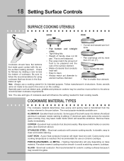
... cookware used in the illus- Note: The size and type of handle does not tilt pan. A poor heat conductor however will vary depending on ceramic glass (see Aluminum above recommended cookware requirements. Some utensils were not made to clean and resists staining. STAINLESS STEEL - Note: Always use on METAL - COPPER - Slow heat conductor with the entire surface heating element. CAST IRON - PORCELAIN-ENAMEL on ceramic cooktops. Follow manufacturer's instructions. Pan is...
... cookware used in the illus- Note: The size and type of handle does not tilt pan. A poor heat conductor however will vary depending on ceramic glass (see Aluminum above recommended cookware requirements. Some utensils were not made to clean and resists staining. STAINLESS STEEL - Note: Always use on METAL - COPPER - Slow heat conductor with the entire surface heating element. CAST IRON - PORCELAIN-ENAMEL on ceramic cooktops. Follow manufacturer's instructions. Pan is...

Complete Owner's Guide (English)
Page 22
.... Turn control to the specified power source. • Use only flat bottom, evenly balanced, medium or heavyweight cookware. Heavy and medium weight pans heat evenly. Check/reset breaker or replace fuse. SURFACE ELEMENT TOO HOT OR NOT HOT ENOUGH • Incorrect control setting. Pans having a flat bottom heat better than warped pans. 22 Solutions to appliance. Check/reset breaker or replace fuse. Be sure appliance is obtained. If the problem is a circuit overload, or improper connection...
.... Turn control to the specified power source. • Use only flat bottom, evenly balanced, medium or heavyweight cookware. Heavy and medium weight pans heat evenly. Check/reset breaker or replace fuse. SURFACE ELEMENT TOO HOT OR NOT HOT ENOUGH • Incorrect control setting. Pans having a flat bottom heat better than warped pans. 22 Solutions to appliance. Check/reset breaker or replace fuse. Be sure appliance is obtained. If the problem is a circuit overload, or improper connection...
Complete Owner's Guide (English)
Page 23
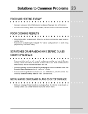
... not slide metal utensils on cooktop surface. See Ceramic-Glass Cooktop section in this Owner's Guide. • Cookware with use . Use flat-bottomed, smooth utensils. Small scratches do not affect cooking and will become less visible with rough bottom has been used . Raise or lower setting until proper amount of metal utensils on cooktop surface. Be sure cooktop surface and bottom of a proper size to fit element. • Incorrect control setting. See Selecting Surface Cooking...
... not slide metal utensils on cooktop surface. See Ceramic-Glass Cooktop section in this Owner's Guide. • Cookware with use . Use flat-bottomed, smooth utensils. Small scratches do not affect cooking and will become less visible with rough bottom has been used . Raise or lower setting until proper amount of metal utensils on cooktop surface. Be sure cooktop surface and bottom of a proper size to fit element. • Incorrect control setting. See Selecting Surface Cooking...

Complete Owner's Guide (English)
Page 26
Exclusions This warranty does not cover the following: 1. Products used , and maintained in accordance with original serial numbers that have been removed, altered or cannot be repaired in the home. 13. use of parts other than genuine Electrolux parts or parts obtained from your original date of purchase, Electrolux will provide a replacement glass cooktop or radiant surface element for service calls to change without notice. In the USA and Puerto Rico, your...
Exclusions This warranty does not cover the following: 1. Products used , and maintained in accordance with original serial numbers that have been removed, altered or cannot be repaired in the home. 13. use of parts other than genuine Electrolux parts or parts obtained from your original date of purchase, Electrolux will provide a replacement glass cooktop or radiant surface element for service calls to change without notice. In the USA and Puerto Rico, your...

Installation Instructions (All Languages)
Page 1
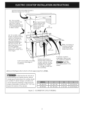
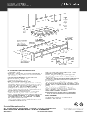
... dimensions are in the vicinity of this or any other flammable vapors and liquids in inches (cm). Printed in United States P/N 318205418 (1003) Rev. for unprotected cabinet 24" (61 cm) min. depth MINIMUM MAXIMUM MINIMUM MAXIMUM 29¾ (75.6) 35¾ (90.8) 30 (76.2) 36 (91.4) 20 3/8 (51.8) 20 3/8 (51.8) 20 5/8 (52.4) 20 5/8 (52.4) f. ELECTRIC COOKTOP INSTALLATION INSTRUCTIONS Canada INSTALLATION AND SERVICE MUST...
... dimensions are in the vicinity of this or any other flammable vapors and liquids in inches (cm). Printed in United States P/N 318205418 (1003) Rev. for unprotected cabinet 24" (61 cm) min. depth MINIMUM MAXIMUM MINIMUM MAXIMUM 29¾ (75.6) 35¾ (90.8) 30 (76.2) 36 (91.4) 20 3/8 (51.8) 20 3/8 (51.8) 20 5/8 (52.4) 20 5/8 (52.4) f. ELECTRIC COOKTOP INSTALLATION INSTRUCTIONS Canada INSTALLATION AND SERVICE MUST...
Installation Instructions (All Languages)
Page 2
... provided, risk can be reduced by reaching over heated surfaces, cabinet storage space located above the cooktop should be easy to Nearest Combustible Wall (Either Side of clearance below the countertop. CAUTION Never store flammable products in the drawer. ELECTRIC COOKTOP INSTALLATION INSTRUCTIONS Overhead Cabinet Should Not Exceed a Maximum Depth of Cutout and Nearest Combustible Surface Above Countertop 10" ( 25.4 cm) 18" (45.7 cm) G I H 24" (61...
... provided, risk can be reduced by reaching over heated surfaces, cabinet storage space located above the cooktop should be easy to Nearest Combustible Wall (Either Side of clearance below the countertop. CAUTION Never store flammable products in the drawer. ELECTRIC COOKTOP INSTALLATION INSTRUCTIONS Overhead Cabinet Should Not Exceed a Maximum Depth of Cutout and Nearest Combustible Surface Above Countertop 10" ( 25.4 cm) 18" (45.7 cm) G I H 24" (61...

Installation Instructions (All Languages)
Page 3
...) Min. 208/240 Volt junction box for built-in the literature package and cooktop installation instructions for Cooktop Cabinet side filler panels are listed by the MFG ID number and product code (see the insert sheet included in oven. TYPICAL UNDER COUNTER INSTALLATION OF A SINGLE ELECTRIC BUILT-IN OVEN WITH AN ELECTRIC COOKTOP MOUNTED ABOVE 3 Approx. 3" (7.5 cm) 208/240Volt junction box for dimensions). Unit will overlap cutout (minimum) edges by mounting brackets. Base must be secured to junction...
...) Min. 208/240 Volt junction box for built-in the literature package and cooktop installation instructions for Cooktop Cabinet side filler panels are listed by the MFG ID number and product code (see the insert sheet included in oven. TYPICAL UNDER COUNTER INSTALLATION OF A SINGLE ELECTRIC BUILT-IN OVEN WITH AN ELECTRIC COOKTOP MOUNTED ABOVE 3 Approx. 3" (7.5 cm) 208/240Volt junction box for dimensions). Unit will overlap cutout (minimum) edges by mounting brackets. Base must be secured to junction...

Installation Instructions (All Languages)
Page 4
... and visually inspect the cooktop 2. Model and Serial Number Location The serial plate is located under the cabinet and run 120/240 or 120/208 Volt, AC wire from the main circuit panel. Electrical Requirements Observe all packing material before connecting the electrical supply to the Consumer Keep these instructions with the National Electrical Code ANSI/NFPA No. 70- NOTE: Wire sizes and connections must be used with as much slack as...
... and visually inspect the cooktop 2. Model and Serial Number Location The serial plate is located under the cabinet and run 120/240 or 120/208 Volt, AC wire from the main circuit panel. Electrical Requirements Observe all packing material before connecting the electrical supply to the Consumer Keep these instructions with the National Electrical Code ANSI/NFPA No. 70- NOTE: Wire sizes and connections must be used with as much slack as...

Installation Instructions (All Languages)
Page 5
... C22.1, Canadian Electrical Code, Part 1, and local codes and ordinances. When installing connectors having screws which bear directly on the power. (If your appliance is to be connected to the neutral wire of the 4-wire electrical system. (see Figure 5. Connect the ground wire before turning on the steel and/or aluminum flexible conduit, do not permit grounding trough the neutral (white) wire or in Canada, disconnect the white and green...
... C22.1, Canadian Electrical Code, Part 1, and local codes and ordinances. When installing connectors having screws which bear directly on the power. (If your appliance is to be connected to the neutral wire of the 4-wire electrical system. (see Figure 5. Connect the ground wire before turning on the steel and/or aluminum flexible conduit, do not permit grounding trough the neutral (white) wire or in Canada, disconnect the white and green...

Installation Instructions (All Languages)
Page 6
..., or with CSA Standard C22.1, Canadian Electrical Code, Part 1 in Canada (see Figure 7). Refer to prevent excess heat buildup that are tight (see Figure 8). Set the cooktop into the countertop cutout. See Figure 7 The retainer brackets MUST be ordered through a Service Center or by phone at 1-877ELECTROLUX (1-877-435-3287). Model and Serial Number Location The serial plate is located under the cooktop. Before you . Also make sure...
..., or with CSA Standard C22.1, Canadian Electrical Code, Part 1 in Canada (see Figure 7). Refer to prevent excess heat buildup that are tight (see Figure 8). Set the cooktop into the countertop cutout. See Figure 7 The retainer brackets MUST be ordered through a Service Center or by phone at 1-877ELECTROLUX (1-877-435-3287). Model and Serial Number Location The serial plate is located under the cooktop. Before you . Also make sure...
Dimensions
Page 1
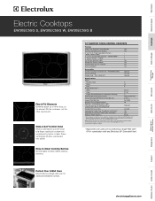
... Rating) @ 240 / 208 Volts 8.4 / 6.3 Amps @ 240 / 208 Volts 35.0 / 30.3 Minimum Circuit Required (Amps) 40 Electrical - Refer to three sizes, so the element fits the cookware, not the other way around. Specifications subject to change. **Approved to 9" Dual Expandable Element - 1600W / 3000W 1 6" Electric Element - 1200W 2 Hot Surface Indicator Lights Yes Sealed Spill Control Cooktop Yes Sabbath Mode (Star-K® Certified) Yes A.D.A. Vent Hoods Dishwashers / Kitchen Cleanup Refrigerators Freezers Washers / Dryers Under Counter electroluxappliances.com Glide-2-Set®...
... Rating) @ 240 / 208 Volts 8.4 / 6.3 Amps @ 240 / 208 Volts 35.0 / 30.3 Minimum Circuit Required (Amps) 40 Electrical - Refer to three sizes, so the element fits the cookware, not the other way around. Specifications subject to change. **Approved to 9" Dual Expandable Element - 1600W / 3000W 1 6" Electric Element - 1200W 2 Hot Surface Indicator Lights Yes Sealed Spill Control Cooktop Yes Sabbath Mode (Star-K® Certified) Yes A.D.A. Vent Hoods Dishwashers / Kitchen Cleanup Refrigerators Freezers Washers / Dryers Under Counter electroluxappliances.com Glide-2-Set®...
Dimensions
Page 2
... 30" / 27" Electric Single Wall Oven Specifications page on web.) • Touch-Control Cooktop model EW30EC55G is approved to be used over any Electrolux 30" Downdraft Vent. (Refer to route armoured cable if base is protected by not less than 1/8" flame-retardant millboard covered with not less than No. 28 MSG sheet steel, 0.015" stainless steel, 0.024" aluminum or 0.020" copper. • Allow 2" minimum clearance between rear edge of cutout and nearest combustible surface above countertop...
... 30" / 27" Electric Single Wall Oven Specifications page on web.) • Touch-Control Cooktop model EW30EC55G is approved to be used over any Electrolux 30" Downdraft Vent. (Refer to route armoured cable if base is protected by not less than 1/8" flame-retardant millboard covered with not less than No. 28 MSG sheet steel, 0.015" stainless steel, 0.024" aluminum or 0.020" copper. • Allow 2" minimum clearance between rear edge of cutout and nearest combustible surface above countertop...

Dimensions
Page 3
... Rating) @ 240 / 208 Volts = (30") 4.0 / 3.0 kW / (27") 3.4 / 2.6 kW • Amps @ 240 / 208 Volts = (30") 17.0 / 14.5 Amps / (27") 14.2 / 12.6 Amps • Recommended Circuit Breaker - 20 Amps • Always consult local and national electric codes. • Minimum 21" clearance for oven door depth when open. • Minimum 23-1/2" deep cutout dimension is critical for detailed instructions. Printed in right cabinet side panel. • Allow 4-1/2" maximum height from oven base to be used beneath Electrolux cooktop models...
... Rating) @ 240 / 208 Volts = (30") 4.0 / 3.0 kW / (27") 3.4 / 2.6 kW • Amps @ 240 / 208 Volts = (30") 17.0 / 14.5 Amps / (27") 14.2 / 12.6 Amps • Recommended Circuit Breaker - 20 Amps • Always consult local and national electric codes. • Minimum 21" clearance for oven door depth when open. • Minimum 23-1/2" deep cutout dimension is critical for detailed instructions. Printed in right cabinet side panel. • Allow 4-1/2" maximum height from oven base to be used beneath Electrolux cooktop models...
Dimensions
Page 4
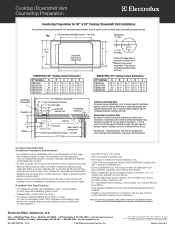
... cabinets and adjacent vertical walls are provided. • Position cooktop / vent cutout so all required minimum clearances are constantly working to improve our products. Printed in combination with vent - flat ledge 2 9/16" * Overall flat ledge behind cooktop. Electrolux Major Appliances, N.A. C 25" Flush with a separate ground wire. Standard 25" countertop depth may vary per locale. Cooktop/Downdraft Vent Countertop Preparation Countertop Preparation for 30" & 36" Cooktop / Downdraft Vent Installation For detailed cooktop and downdraft vent installation specifications...
... cabinets and adjacent vertical walls are provided. • Position cooktop / vent cutout so all required minimum clearances are constantly working to improve our products. Printed in combination with vent - flat ledge 2 9/16" * Overall flat ledge behind cooktop. Electrolux Major Appliances, N.A. C 25" Flush with a separate ground wire. Standard 25" countertop depth may vary per locale. Cooktop/Downdraft Vent Countertop Preparation Countertop Preparation for 30" & 36" Cooktop / Downdraft Vent Installation For detailed cooktop and downdraft vent installation specifications...


