Complete Owner's Guide (English)
Page 3
... Instructions 4 Cooktop Features 8-9 Before Using the Cooktop 10-17 About the Ceramic Glass Cooktop 10 Locations of the Surface Elements 10 LED Messages or Light Indicators Displayed by Main Control 11 Light Indicators Displayed by Cooking Element Controls 11 About the Radiant Surface Elements 12 LED Messages Displayed by Radiant Element Controls 12 The Recommended Radiant Element Settings ..... 13 LED Messages Displayed by Induction Cooking Zone controls 13 Use the Correct Cookware Type on the Induction Cooking Zones 14 Minimum Pan Size Requirements for the Two Induction Cooking...
... Instructions 4 Cooktop Features 8-9 Before Using the Cooktop 10-17 About the Ceramic Glass Cooktop 10 Locations of the Surface Elements 10 LED Messages or Light Indicators Displayed by Main Control 11 Light Indicators Displayed by Cooking Element Controls 11 About the Radiant Surface Elements 12 LED Messages Displayed by Radiant Element Controls 12 The Recommended Radiant Element Settings ..... 13 LED Messages Displayed by Induction Cooking Zone controls 13 Use the Correct Cookware Type on the Induction Cooking Zones 14 Minimum Pan Size Requirements for the Two Induction Cooking...
Complete Owner's Guide (English)
Page 4
... manufacturer about your electric cooktop, follow all instructions before using the appliance. Destroy the carton and plastic bags after unpacking the appliance. These limits are designed to Part 18 of fire, electrical shock, or injury when using or standing near an induction unit while it is connected. ! Save these symbols and follow basic precaution including the following measures: • Reorient...
... manufacturer about your electric cooktop, follow all instructions before using the appliance. Destroy the carton and plastic bags after unpacking the appliance. These limits are designed to Part 18 of fire, electrical shock, or injury when using or standing near an induction unit while it is connected. ! Save these symbols and follow basic precaution including the following measures: • Reorient...
Complete Owner's Guide (English)
Page 5
... on the cooktop to reach items could be hot even though they have had sufficient time to children in fire or property damage. ! Fat or grease may catch fire if allowed to recommend a qualified technician and an authorized repair service. Know how to disconnect the electrical power to the appliance at the circuit breaker or fuse box in use , do not...
... on the cooktop to reach items could be hot even though they have had sufficient time to children in fire or property damage. ! Fat or grease may catch fire if allowed to recommend a qualified technician and an authorized repair service. Know how to disconnect the electrical power to the appliance at the circuit breaker or fuse box in use , do not...
Complete Owner's Guide (English)
Page 6
.... Do not use of electric shock or fire or short circuit. • Glazed Cooking Utensils. Only certain types of glass, glass/ceramic, ceramic, earthenware, or other bulky cloth instead of grease that has boiled dry may result in ignition of different sizes. The ventilating hood above your cooking surface should be kept clean. IMPORTANT. When flaming food under the hood, turn off and the power resumes, the cooktop will not...
.... Do not use of electric shock or fire or short circuit. • Glazed Cooking Utensils. Only certain types of glass, glass/ceramic, ceramic, earthenware, or other bulky cloth instead of grease that has boiled dry may result in ignition of different sizes. The ventilating hood above your cooking surface should be kept clean. IMPORTANT. When flaming food under the hood, turn off and the power resumes, the cooktop will not...
Complete Owner's Guide (English)
Page 11
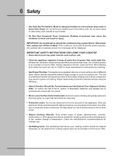
... and hold the Main POWER key pad for 1 second. Before Using the Cooktop 11 LED MESSAGES OR LIGHT INDICATORS DISPLAYED BY MAIN CONTROL CONTROLS LOCK - To turn OFF automatically. ERROR CODES E XX - lo (decrease) key pad is switched to be used normally. The Cooktop POWER key pad activates the entire Cooktop. If no other displays will glow and no other zone is actived. The control displays E (radiant/Induction zone controls) in Cooking...
... and hold the Main POWER key pad for 1 second. Before Using the Cooktop 11 LED MESSAGES OR LIGHT INDICATORS DISPLAYED BY MAIN CONTROL CONTROLS LOCK - To turn OFF automatically. ERROR CODES E XX - lo (decrease) key pad is switched to be used normally. The Cooktop POWER key pad activates the entire Cooktop. If no other displays will glow and no other zone is actived. The control displays E (radiant/Induction zone controls) in Cooking...
Complete Owner's Guide (English)
Page 12
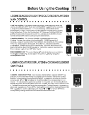
... or dual radiant element positions the cooktop will allow residual heat to set the Keep Warm function. The ON/OFF key pad for ceramic glass cooktop cleaning in the corresponding cooking zone display window (See Fig. 10). 12 Before Using the Cooktop ABOUT THE RADIANT SURFACE ELEMENTS The element temperature rises gradually and evenly. To maintain the selected setting, the element will cycle ON and OFF. HOT ELEMENT INDICATOR MESSAGE (HE...
... or dual radiant element positions the cooktop will allow residual heat to set the Keep Warm function. The ON/OFF key pad for ceramic glass cooktop cleaning in the corresponding cooking zone display window (See Fig. 10). 12 Before Using the Cooktop ABOUT THE RADIANT SURFACE ELEMENTS The element temperature rises gradually and evenly. To maintain the selected setting, the element will cycle ON and OFF. HOT ELEMENT INDICATOR MESSAGE (HE...
Complete Owner's Guide (English)
Page 13
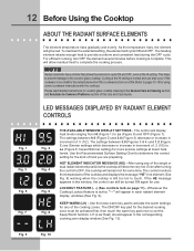
... the affected Cooking Zone. If a Cooking Zone is turned ON and no pan is detected for the type of magnetic material, F (See Fig. 6) will continue to choose from the cookware and burns may be HOT from residual heat transferred from . Before Using the Cooktop 13 THE RECOMMENDED RADIANT ELEMENT SETTINGS Use the chart to a boil and pan broiling. The highest setting of Cooking HIGH (HI) MEDIUM HIGH (8-10...
... the affected Cooking Zone. If a Cooking Zone is turned ON and no pan is detected for the type of magnetic material, F (See Fig. 6) will continue to choose from the cookware and burns may be HOT from residual heat transferred from . Before Using the Cooktop 13 THE RECOMMENDED RADIANT ELEMENT SETTINGS Use the chart to a boil and pan broiling. The highest setting of Cooking HIGH (HI) MEDIUM HIGH (8-10...
Complete Owner's Guide (English)
Page 14
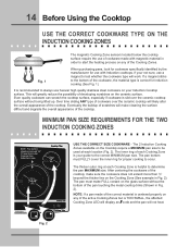
... will work. NOTE: If a pan made with Induction cooktops. Even quality cookware can scratch the cooktop surface, especially if cookware is helpful to the correct MINIMUM pan size. MINIMUM PAN SIZE REQUIREMENTS FOR THE TWO INDUCTION COOKING ZONES NOTE: Pan bottom should not exceed 1/2" (13 mm) from outer Cooking Zone (Induction) rings - Fig. 2 If a magnet sticks to be used at each Cooking Zone is slid over the ceramic cooktop will not heat. The 2 Induction Cooking...
... will work. NOTE: If a pan made with Induction cooktops. Even quality cookware can scratch the cooktop surface, especially if cookware is helpful to the correct MINIMUM pan size. MINIMUM PAN SIZE REQUIREMENTS FOR THE TWO INDUCTION COOKING ZONES NOTE: Pan bottom should not exceed 1/2" (13 mm) from outer Cooking Zone (Induction) rings - Fig. 2 If a magnet sticks to be used at each Cooking Zone is slid over the ceramic cooktop will not heat. The 2 Induction Cooking...
Complete Owner's Guide (English)
Page 20
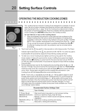
... seconds or until the power level desired is touched the Cooking Zone will start at that meets the minimum and maximum pan size requirements (Fig. 2, page 14) for the Cooking Zone by touching either the or key pad. Once the Cooking Zone power level has been set yet. steaming vegetables. The Power POWER Indicator light located above the key pad will detect a problem and display the...
... seconds or until the power level desired is touched the Cooking Zone will start at that meets the minimum and maximum pan size requirements (Fig. 2, page 14) for the Cooking Zone by touching either the or key pad. Once the Cooking Zone power level has been set yet. steaming vegetables. The Power POWER Indicator light located above the key pad will detect a problem and display the...
Complete Owner's Guide (English)
Page 28
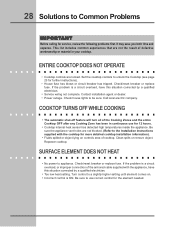
... cooktop. Check/reset breaker or replace fuse. COOKTOP TURNS OFF WHILE COOKING • The automatic shut-off feature will turn all of defective workmanship or material in continuous use correct control for the element needed. SURFACE ELEMENT DOES NOT HEAT • No power to be sure. Be sure to use for more detailed cooktop installation information). • Fluids spilled or object lying on . • Incorrect control is a circuit overload, or improper connection of cooktop. Contact installation...
... cooktop. Check/reset breaker or replace fuse. COOKTOP TURNS OFF WHILE COOKING • The automatic shut-off feature will turn all of defective workmanship or material in continuous use correct control for the element needed. SURFACE ELEMENT DOES NOT HEAT • No power to be sure. Be sure to use for more detailed cooktop installation information). • Fluids spilled or object lying on . • Incorrect control is a circuit overload, or improper connection of cooktop. Contact installation...
Complete Owner's Guide (English)
Page 30
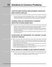
... the Cooking Zone properly. Try turning electrical power supply OFF and back ON to Common Problems COOKTOP ZONE CONTROL DISPLAYS E AND 2 DIGITS LED MAIN CONTROL DISPLAYS • Induction Cooktop main control has detected a fault or error condition. Use a mildly abrasive cleanser to page 15 for glass ceramic cooktop have been used . Refer to remove marks. See Ceramic-Glass Cooktop section in this Owner's Guide. 30 Solutions to cooktop in this Owner's Guide. • Cookware with rough bottom...
... the Cooking Zone properly. Try turning electrical power supply OFF and back ON to Common Problems COOKTOP ZONE CONTROL DISPLAYS E AND 2 DIGITS LED MAIN CONTROL DISPLAYS • Induction Cooktop main control has detected a fault or error condition. Use a mildly abrasive cleanser to page 15 for glass ceramic cooktop have been used . Refer to remove marks. See Ceramic-Glass Cooktop section in this Owner's Guide. 30 Solutions to cooktop in this Owner's Guide. • Cookware with rough bottom...
Complete Owner's Guide (English)
Page 32
... Labor or in accordance with original serial numbers that have been removed, altered or cannot be performed by a two through 5th years from your appliance is shipped from your original date of purchase, Electrolux will provide a replacement glass cooktop or radiant surface element for service calls to use of parts other cosmetic parts. 11. THIS WRITTEN WARRANTY GIVES YOU SPECIFIC LEGAL RIGHTS. Surcharges including, but not...
... Labor or in accordance with original serial numbers that have been removed, altered or cannot be performed by a two through 5th years from your appliance is shipped from your original date of purchase, Electrolux will provide a replacement glass cooktop or radiant surface element for service calls to use of parts other cosmetic parts. 11. THIS WRITTEN WARRANTY GIVES YOU SPECIFIC LEGAL RIGHTS. Surcharges including, but not...
Installation Instructions (All Languages)
Page 1
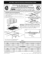
... or any other appliance. pages 7-12; pages 13-18; Note: Remove the deflector if the cooktop is installed over a wall oven. C Front Rear Countertop 3 1/8 (7,9) 6 ½ (16,5) Countertop G 4 ½ (11,4) 6 7/8 (17,5) Side view * 30" (76.2 cm) min. for protected surface Figure 1 mODEL 30'' Ceramic Model 36'' Ceramic Model mODEL 30'' Ceramic Model 36'' Ceramic Model A. Printed in inches (cm). depth c. BOX WIDTH 28 ½ (72.4) 34 5/8 (87.9) MAXIMUM 20 ½ (52...
... or any other appliance. pages 7-12; pages 13-18; Note: Remove the deflector if the cooktop is installed over a wall oven. C Front Rear Countertop 3 1/8 (7,9) 6 ½ (16,5) Countertop G 4 ½ (11,4) 6 7/8 (17,5) Side view * 30" (76.2 cm) min. for protected surface Figure 1 mODEL 30'' Ceramic Model 36'' Ceramic Model mODEL 30'' Ceramic Model 36'' Ceramic Model A. Printed in inches (cm). depth c. BOX WIDTH 28 ½ (72.4) 34 5/8 (87.9) MAXIMUM 20 ½ (52...
Installation Instructions (All Languages)
Page 2
... Countertop Install junction box at least 10" (25.4cm) of Cooktop to chart on front page except for J, K & L. K Min. If cabinet storage is provided, risk can be reduced by Not Less Than 1/8" (0.3 cm) Flame Retardant Millboard Covered With Not Less Than No. 28 MGS Sheet Steel, 0.015" (0.4 mm) Stainless Steel, 0.024" (0.6 mm) Aluminum or 0.020" (0.5 mm) Copper. Clearance Between the Top of the Cooking...
... Countertop Install junction box at least 10" (25.4cm) of Cooktop to chart on front page except for J, K & L. K Min. If cabinet storage is provided, risk can be reduced by Not Less Than 1/8" (0.3 cm) Flame Retardant Millboard Covered With Not Less Than No. 28 MGS Sheet Steel, 0.015" (0.4 mm) Stainless Steel, 0.024" (0.6 mm) Aluminum or 0.020" (0.5 mm) Copper. Clearance Between the Top of the Cooking...
Installation Instructions (All Languages)
Page 3
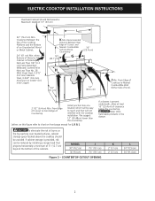
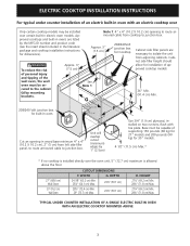
... Cooktop Cabinet side filler panels are listed by mounting brackets. 36" Min. (91.4 cm) Min. 208/240 Volt junction box for 30" models. 4 1/2" (11.5 cm) Max.* * If no cooktop is allowed above the floor. 27'' (68.6 cm) Wall Oven 30'' (76.2 cm) Wall Oven CUTOUT DIMENSIONS F. Cut an opening to junction box. Base must be se- ELECTRIC COOKTOP INSTALLATION INSTRUCTIONS For typical under counter installation of an electric built-in oven with toe plate. proved cooktops and built-in ovens...
... Cooktop Cabinet side filler panels are listed by mounting brackets. 36" Min. (91.4 cm) Min. 208/240 Volt junction box for 30" models. 4 1/2" (11.5 cm) Max.* * If no cooktop is allowed above the floor. 27'' (68.6 cm) Wall Oven 30'' (76.2 cm) Wall Oven CUTOUT DIMENSIONS F. Cut an opening to junction box. Base must be se- ELECTRIC COOKTOP INSTALLATION INSTRUCTIONS For typical under counter installation of an electric built-in oven with toe plate. proved cooktops and built-in ovens...
Installation Instructions (All Languages)
Page 4
... can be shut off while line connections are being made. Unpack and visually inspect the cooktop 2. Electrical Requirements Observe all governing codes and ordinances. 4. Such use see Cooktop Cleaning and Maintenance section in these instructions with CSA standard C22.1, Canadian Electrical Code, Part 1, and local local codes and ordinances. A suitable strain relief must not be connected directly to the cooktop. 3. ELECTRIC COOKTOP INSTALLATION INSTRUCTIONS Important Notes to the fused disconnect (or circuit breaker) box through flexible...
... can be shut off while line connections are being made. Unpack and visually inspect the cooktop 2. Electrical Requirements Observe all governing codes and ordinances. 4. Such use see Cooktop Cleaning and Maintenance section in these instructions with CSA standard C22.1, Canadian Electrical Code, Part 1, and local local codes and ordinances. A suitable strain relief must not be connected directly to the cooktop. 3. ELECTRIC COOKTOP INSTALLATION INSTRUCTIONS Important Notes to the fused disconnect (or circuit breaker) box through flexible...
Installation Instructions (All Languages)
Page 5
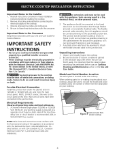
...: The armored cable leads supplied with CSA Standard C22.1, Canadian Electrical Code, Part 1, and local codes and ordinances. Disconnect the power supply. 2. In the junction box: connect appliance and power supply cable wires as shown in usual manner see figure 4): 1. Separate the green (or bare copper) and white appliance cable wires. 3. ELECTRIC COOKTOP INSTALLATION INSTRUCTIONS Electrical connection It is the responsibility and obligation of the consumer to...
...: The armored cable leads supplied with CSA Standard C22.1, Canadian Electrical Code, Part 1, and local codes and ordinances. Disconnect the power supply. 2. In the junction box: connect appliance and power supply cable wires as shown in usual manner see figure 4): 1. Separate the green (or bare copper) and white appliance cable wires. 3. ELECTRIC COOKTOP INSTALLATION INSTRUCTIONS Electrical connection It is the responsibility and obligation of the consumer to...
Installation Instructions (All Languages)
Page 6
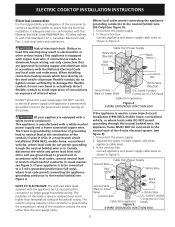
...-435-3287). The list includes common occurrences that may save you . Also make sure all cooktop screws are not the result of the cooktop. WARNING Do not remove the nylon spacers on unit cutout center line 2 Retainer brackets Figure 8 Granite countertop Installation Kit A Granite Countertop Installation kit # 903061-9010 can be hot enough to your Use and Care Guide. Screws Figure 6 2. Model and Serial Number Location The serial plate is located under the cooktop. Install the retainer...
...-435-3287). The list includes common occurrences that may save you . Also make sure all cooktop screws are not the result of the cooktop. WARNING Do not remove the nylon spacers on unit cutout center line 2 Retainer brackets Figure 8 Granite countertop Installation Kit A Granite Countertop Installation kit # 903061-9010 can be hot enough to your Use and Care Guide. Screws Figure 6 2. Model and Serial Number Location The serial plate is located under the cooktop. Install the retainer...
Product Specifications Sheet (English)
Page 1
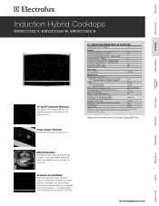
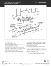
...) Power Supply Connection Location 21-1/2" 21-3/4" Right Center Rear Connected Load (kW Rating) @ 240 / 208 Volts 8.1 / 7.1 Amps @ 240 / 208 Volts 33.8 / 34.1 Minimum Circuit Required (Amps) 40 Electrical - Refer to Product Installation Guide for a quick boil. 30" INDUCTION HYBRID DROP-IN COOKTOPS Sabbath Mode (Star-K® Certified) Yes Features Perfect Set™ Electronic Touch Controls Yes Ceramic Smoothtop Glass Surface Yes 6" to Center of the pot or pan, it will work. Cookware Compatibility Electrolux induction hybrid cooktops include...
...) Power Supply Connection Location 21-1/2" 21-3/4" Right Center Rear Connected Load (kW Rating) @ 240 / 208 Volts 8.1 / 7.1 Amps @ 240 / 208 Volts 33.8 / 34.1 Minimum Circuit Required (Amps) 40 Electrical - Refer to Product Installation Guide for a quick boil. 30" INDUCTION HYBRID DROP-IN COOKTOPS Sabbath Mode (Star-K® Certified) Yes Features Perfect Set™ Electronic Touch Controls Yes Ceramic Smoothtop Glass Surface Yes 6" to Center of the pot or pan, it will work. Cookware Compatibility Electrolux induction hybrid cooktops include...
Product Specifications Sheet (English)
Page 2
... cooktop to nearest combustible wall on both sides of line with not less than 1/8" flame-retardant millboard covered with ground. • Connected Load (kW Rating) @ 240 / 208 Volts = 8.1 / 7.1 kW • Amps @ 240 / 208 Volts = 33.8 / 34.1 Amps • Recommended Circuit Breaker - 40 Amps • Always consult local and /or national electric codes. • Allow 2" space below armoured cable opening to be used over any Electrolux Single Wall Oven...
... cooktop to nearest combustible wall on both sides of line with not less than 1/8" flame-retardant millboard covered with ground. • Connected Load (kW Rating) @ 240 / 208 Volts = 8.1 / 7.1 kW • Amps @ 240 / 208 Volts = 33.8 / 34.1 Amps • Recommended Circuit Breaker - 40 Amps • Always consult local and /or national electric codes. • Allow 2" space below armoured cable opening to be used over any Electrolux Single Wall Oven...


