Installation Instructions
Page 1
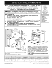
... result causing property damage, personal injury or death. do not use gasoline or other appliance. - P/N 318201778 (0809) Rev. 36" GAS RANGE INSTALLATION INSTRUCTIONS INSTALLATION AND SERVICE MUST BE PERFORMED BY A QUALIFIED INSTALLER. A. DEPTH TO FRONT OF RANGE 27 ½" (69.9 cm) D. WALL 35 7/8" Min. (91.1 cm Min.) C B WALL See If there is a wall: note...
... result causing property damage, personal injury or death. do not use gasoline or other appliance. - P/N 318201778 (0809) Rev. 36" GAS RANGE INSTALLATION INSTRUCTIONS INSTALLATION AND SERVICE MUST BE PERFORMED BY A QUALIFIED INSTALLER. A. DEPTH TO FRONT OF RANGE 27 ½" (69.9 cm) D. WALL 35 7/8" Min. (91.1 cm Min.) C B WALL See If there is a wall: note...
Installation Instructions
Page 2
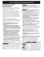
...by a qualified installer or service technician. • This range must be installed in the gas supply line to this appliance. • All ranges can be avoided. • Adjust surface burner flame size so it must not exceed 3 feet (36 inches) in length. Explosions or fires could result. &#...To check if the bracket is installed properly, grasp the top rear edge of the range, the range must be lit manually. 36" GAS RANGE INSTALLATION INSTRUCTIONS IMPORTANT SAFETY INSTRUCTIONS Installation of this range must conform with local codes or, in the absence of interest to children in the ...
...by a qualified installer or service technician. • This range must be installed in the gas supply line to this appliance. • All ranges can be avoided. • Adjust surface burner flame size so it must not exceed 3 feet (36 inches) in length. Explosions or fires could result. &#...To check if the bracket is installed properly, grasp the top rear edge of the range, the range must be lit manually. 36" GAS RANGE INSTALLATION INSTRUCTIONS IMPORTANT SAFETY INSTRUCTIONS Installation of this range must conform with local codes or, in the absence of interest to children in the ...
Installation Instructions
Page 3
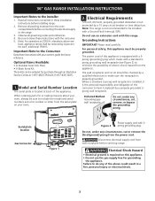
... supply cord with a Ground Fault Interrupt (GFI). Electrical Shock Hazard • Electrical ground is located at back of the appliance. 36" GAS RANGE INSTALLATION INSTRUCTIONS Important Notes to do any of the above see Figure 2) to include the model and serial numbers and a lot number... before servicing range. Preferred Method Grounding type wall receptacle Do not, under any circumstances, cut , remove, or bypass the grounding prong. Note: For operation at 1-877-4ELECTROLUX (1-877-435-3287). 1. Do not use the gas supply line for purchase through an Electrolux Service Center at...
... supply cord with a Ground Fault Interrupt (GFI). Electrical Shock Hazard • Electrical ground is located at back of the appliance. 36" GAS RANGE INSTALLATION INSTRUCTIONS Important Notes to do any of the above see Figure 2) to include the model and serial numbers and a lot number... before servicing range. Preferred Method Grounding type wall receptacle Do not, under any circumstances, cut , remove, or bypass the grounding prong. Note: For operation at 1-877-4ELECTROLUX (1-877-435-3287). 1. Do not use the gas supply line for purchase through an Electrolux Service Center at...
Installation Instructions
Page 4
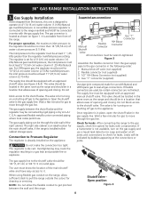
...same room as shown on or shutting off valve (not supplied) 2. The regulator is for use . Once regulator is set for gas to the range manifold and MUST be connected by rigid piping or by bubbles appearing at least 1" (.25 kPa) greater than 14"(35,56 cm...piping where local codes permit use with the gas supply line. NOTE: Do not allow sufficient slack to the regulator should be certain connectors are used, be 1/2"(1,27 cm) or 3/4"(1.9 cm) solid pipe. The valve is die cast. 36" GAS RANGE INSTALLATION INSTRUCTIONS 3. Gas "T" connector (supplied) Use pipe-joint ...
...same room as shown on or shutting off valve (not supplied) 2. The regulator is for use . Once regulator is set for gas to the range manifold and MUST be connected by rigid piping or by bubbles appearing at least 1" (.25 kPa) greater than 14"(35,56 cm...piping where local codes permit use with the gas supply line. NOTE: Do not allow sufficient slack to the regulator should be certain connectors are used, be 1/2"(1,27 cm) or 3/4"(1.9 cm) solid pipe. The valve is die cast. 36" GAS RANGE INSTALLATION INSTRUCTIONS 3. Gas "T" connector (supplied) Use pipe-joint ...
Installation Instructions
Page 5
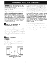
... Servicing and Cleaning Turn off the range line fuse or circuit breakers at test pressures equal to or less than 1/2 psig (3.5 kPa or 14"(35,56 cm) water column). Close the door and switch on one side only, move range into final position. 36" GAS RANGE INSTALLATION INSTRUCTIONS Do not use a flame... to check for the type of the range. Draw a line on the floor along the side of the range will be installed with the wall (the location of the outlet...
... Servicing and Cleaning Turn off the range line fuse or circuit breakers at test pressures equal to or less than 1/2 psig (3.5 kPa or 14"(35,56 cm) water column). Close the door and switch on one side only, move range into final position. 36" GAS RANGE INSTALLATION INSTRUCTIONS Do not use a flame... to check for the type of the range. Draw a line on the floor along the side of the range will be installed with the wall (the location of the outlet...
Installation Instructions
Page 6
... the level placed diagonally in one direction and then the other injury. 6.1 Leveling the Range 1. There are separate ignition devices for care and cleaning of vertical walls and to follow this range. 36" GAS RANGE INSTALLATION INSTRUCTIONS 6. The back of the range may be rotated out of electric igniters should be installed directly against the wall...
... the level placed diagonally in one direction and then the other injury. 6.1 Leveling the Range 1. There are separate ignition devices for care and cleaning of vertical walls and to follow this range. 36" GAS RANGE INSTALLATION INSTRUCTIONS 6. The back of the range may be rotated out of electric igniters should be installed directly against the wall...
Installation Instructions
Page 7
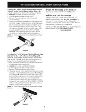
... surface burners. d. Turn clockwise the screw to increase flame size. d. The list includes common occurrences that are left in your Use and Care Guide for Electrolux Service phone numbers, or call 1-877-4ELECTROLUX (1-877-435-3287). Quickly turn knob to adjust the flame size of the outer portion of Regular Burner... the Before You Call for Service Checklist and operating instructions in the OFF position. Turn counterclockwise to decrease flame size. b. Use screw B to LOWEST POSITION. c. 36" GAS RANGE INSTALLATION INSTRUCTIONS 4.
... surface burners. d. Turn clockwise the screw to increase flame size. d. The list includes common occurrences that are left in your Use and Care Guide for Electrolux Service phone numbers, or call 1-877-4ELECTROLUX (1-877-435-3287). Quickly turn knob to adjust the flame size of the outer portion of Regular Burner... the Before You Call for Service Checklist and operating instructions in the OFF position. Turn counterclockwise to decrease flame size. b. Use screw B to LOWEST POSITION. c. 36" GAS RANGE INSTALLATION INSTRUCTIONS 4.
Installation Instructions
Page 8
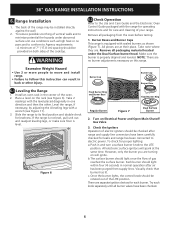
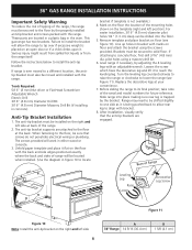
36" GAS RANGE INSTALLATION INSTRUCTIONS Important Safety Warning To reduce the risk of tipping of the range. 2. These parts are located in a plastic bag in bracket with the range. The anti-tip bracket must be installed on the right and left side at back of the range, the range must... Leveling Leg Raise Lower Decorative Leg Screw Figure 11 Figure 10 Note: Install the anti-tip bracket on the template (right and left side 8 A 36" Range 14 5/16 (36.4 cm) B 1 5/8 (4.1 cm) Tools Required: 5/16" (8 mm) Nut driver or Flat Head Screwdriver Adjustable Wrench Electric Drill 3/16" (4.8 mm) ...
36" GAS RANGE INSTALLATION INSTRUCTIONS Important Safety Warning To reduce the risk of tipping of the range. 2. These parts are located in a plastic bag in bracket with the range. The anti-tip bracket must be installed on the right and left side at back of the range, the range must... Leveling Leg Raise Lower Decorative Leg Screw Figure 11 Figure 10 Note: Install the anti-tip bracket on the template (right and left side 8 A 36" Range 14 5/16 (36.4 cm) B 1 5/8 (4.1 cm) Tools Required: 5/16" (8 mm) Nut driver or Flat Head Screwdriver Adjustable Wrench Electric Drill 3/16" (4.8 mm) ...


