Wiring Diagram
Page 3
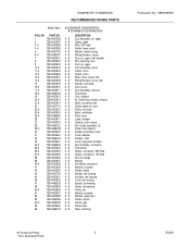
..., sensor A B Duct, air, upper, with bracket A B Nut, mounting, duct A B Duct, air, upper A B Cam Assembly, louver A B Switch, micro A B Switch, micro A B Motor, drive, louver cam A B Wiring Harness, louver cam A B Bracket, cam plate A B Cam, louver A B Duct Assembly, exhaust A B Thermostat A B Duct, exhaust A B Air Guide Assy, heater, w/motor A B Motor, convection fan A B Guide, heater air, duct A B Pulley, fan motor A B Motor, ventilation A B Filter, noise A B Lamp, halogen A B Cabinet, outer casing A B Nut, holder assembly, (2) A B Power Cord, electric A B Damper Assembly, hood A B Cover...
..., sensor A B Duct, air, upper, with bracket A B Nut, mounting, duct A B Duct, air, upper A B Cam Assembly, louver A B Switch, micro A B Switch, micro A B Motor, drive, louver cam A B Wiring Harness, louver cam A B Bracket, cam plate A B Cam, louver A B Duct Assembly, exhaust A B Thermostat A B Duct, exhaust A B Air Guide Assy, heater, w/motor A B Motor, convection fan A B Guide, heater air, duct A B Pulley, fan motor A B Motor, ventilation A B Filter, noise A B Lamp, halogen A B Cabinet, outer casing A B Nut, holder assembly, (2) A B Power Cord, electric A B Damper Assembly, hood A B Cover...
Wiring Diagram
Page 5
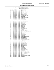
... Lens, lamp cover, glass A B Motor, drive A B Coupler, motor/turntable A B Support, rack A B Stirrer Assembly A B Holder, stirrer A B Fan Blade, stirrer A B Cover Assembly, stirrer A B Support, stirrer A B Cover, stirrer A B Latch Assembly A B Switch, micro, (2) A B Switch, micro A B Latch Body A B Lever, switch, lower A B Rack, wire A B Grille Assembly, front A B Control Panel Assy, w/touch pad A B Housing, fan bearing A B Clip, ground, grille A B Spring, louver A B Hinge, grille, left A B Cover, front A B Cover, lower plate, insulator A B Air Guide, bottom A B Filter, air, charcoal A B Guide...
... Lens, lamp cover, glass A B Motor, drive A B Coupler, motor/turntable A B Support, rack A B Stirrer Assembly A B Holder, stirrer A B Fan Blade, stirrer A B Cover Assembly, stirrer A B Support, stirrer A B Cover, stirrer A B Latch Assembly A B Switch, micro, (2) A B Switch, micro A B Latch Body A B Lever, switch, lower A B Rack, wire A B Grille Assembly, front A B Control Panel Assy, w/touch pad A B Housing, fan bearing A B Clip, ground, grille A B Spring, louver A B Hinge, grille, left A B Cover, front A B Cover, lower plate, insulator A B Air Guide, bottom A B Filter, air, charcoal A B Guide...
Wiring Diagram
Page 7
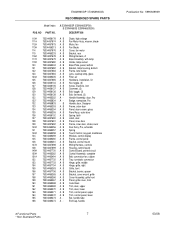
... A B Motor, fan 113# 75304456213 A B Fan Blade 114 75304457676 A B Cover, fan motor 115 75304465233 A B Bracket, rear 116# 75304457678 A B Wiring Harness, A 117# 75304457679 A B Base Assembly, with lamp 119# 75304457680 A B Holder, lamp socket 120 75304465234 A B Base Plate, panel, bottom 121 75304457682 A B Bracket, lamp housing, bottom 122 75304457683 A B Frame, lens holder 123 75304457684 A B Lens, cooktop lamp, glass 124# 75304465235 A B Filter, air 125 75304457685 A B Hardware, installation, kit 126 75304456134 A B Nut, toggle, (3) 127 75304456135 A B Screw, machine...
... A B Motor, fan 113# 75304456213 A B Fan Blade 114 75304457676 A B Cover, fan motor 115 75304465233 A B Bracket, rear 116# 75304457678 A B Wiring Harness, A 117# 75304457679 A B Base Assembly, with lamp 119# 75304457680 A B Holder, lamp socket 120 75304465234 A B Base Plate, panel, bottom 121 75304457682 A B Bracket, lamp housing, bottom 122 75304457683 A B Frame, lens holder 123 75304457684 A B Lens, cooktop lamp, glass 124# 75304465235 A B Filter, air 125 75304457685 A B Hardware, installation, kit 126 75304456134 A B Nut, toggle, (3) 127 75304456135 A B Screw, machine...
Installation Instructions
Page 2
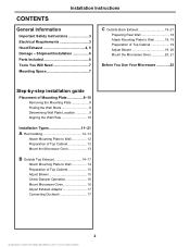
... Important Safety Instructions 3 Electrical Requirements 3 Hood Exhaust 4, 5 Damage - Shipment/Installation 6 Parts Included 6 Tools You Will Need 7 Mounting Space 7 C Outside Back Exhaust 18-21 Preparing Rear Wall 18 Attach Mounting Plate to Wall 18, 19 Preparation of Top Cabinet 19 Adjust Blower 19, 20 Mount the Microwave Oven 20, 21 Before You Use Your Microwave 22 Step-by-step installation guide Placement of Mounting Plate 8-10 Removing the Mounting Plate 8 Finding the Wall Studs 8 Determining Wall Plate Location 9 Aligning the Wall Plate 10 Installation Types 11...
... Important Safety Instructions 3 Electrical Requirements 3 Hood Exhaust 4, 5 Damage - Shipment/Installation 6 Parts Included 6 Tools You Will Need 7 Mounting Space 7 C Outside Back Exhaust 18-21 Preparing Rear Wall 18 Attach Mounting Plate to Wall 18, 19 Preparation of Top Cabinet 19 Adjust Blower 19, 20 Mount the Microwave Oven 20, 21 Before You Use Your Microwave 22 Step-by-step installation guide Placement of Mounting Plate 8-10 Removing the Mounting Plate 8 Finding the Wall Studs 8 Determining Wall Plate Location 9 Aligning the Wall Plate 10 Installation Types 11...
Installation Instructions
Page 3
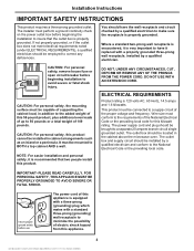
... ANY CIRCUMSTANCES, CUT, DEFORM OR REMOVE ANY OF THE PRONGS FROM THE POWER CORD. The power supply cord and plug should be brought to a supply circuit of the proper voltage and frequency. The outlet box should be located in the cabinet above the microwave oven. Installation Instructions IMPORTANT SAFETY INSTRUCTIONS This product requires a three-prong grounded outlet. DO NOT USE WITH AN EXTENSION CORD. ELECTRICAL REQUIREMENTS Product...
... ANY CIRCUMSTANCES, CUT, DEFORM OR REMOVE ANY OF THE PRONGS FROM THE POWER CORD. The power supply cord and plug should be brought to a supply circuit of the proper voltage and frequency. The outlet box should be located in the cabinet above the microwave oven. Installation Instructions IMPORTANT SAFETY INSTRUCTIONS This product requires a three-prong grounded outlet. DO NOT USE WITH AN EXTENSION CORD. ELECTRICAL REQUIREMENTS Product...

Installation Instructions
Page 6
... of the customer. • If the unit is damaged by the installer (if other than the customer), repair or replacement must be made by arrangement between customer and installer. ADDITIONAL PARTS PART TOP CABINET TEMPLATE QUANTITY Top Cabinet 1 Template REAR WALL TEMPLATE Rear Wall 1 Template IInnssttraullcatitoionns Installation 1 Instructions Separately 2 Packed Grease Filters Exhaust 1 adaptor 6 NOTE: Some extra parts are included. Installation Instructions DAMAGE - Check to the store in which it was bought for metal...
... of the customer. • If the unit is damaged by the installer (if other than the customer), repair or replacement must be made by arrangement between customer and installer. ADDITIONAL PARTS PART TOP CABINET TEMPLATE QUANTITY Top Cabinet 1 Template REAR WALL TEMPLATE Rear Wall 1 Template IInnssttraullcatitoionns Installation 1 Instructions Separately 2 Packed Grease Filters Exhaust 1 adaptor 6 NOTE: Some extra parts are included. Installation Instructions DAMAGE - Check to the store in which it was bought for metal...
Installation Instructions
Page 7
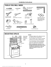
... pieces, if needed for top cabinet spacing (used on the top cabinet template for exhaust duct preparation. • When installing the microwave oven beneath smooth flat cabinets be careful to follow the instructions on recessed bottom cabinet installations only) Safety goggles Level Duct and masking tape MOUNTING SPACE 16-½ " 30" 5" 33"min. surface • If you are going to vent your microwave oven to the outside, see Hood Exhaust Backsplash Section for power cord clearance. 7
... pieces, if needed for top cabinet spacing (used on the top cabinet template for exhaust duct preparation. • When installing the microwave oven beneath smooth flat cabinets be careful to follow the instructions on recessed bottom cabinet installations only) Safety goggles Level Duct and masking tape MOUNTING SPACE 16-½ " 30" 5" 33"min. surface • If you are going to vent your microwave oven to the outside, see Hood Exhaust Backsplash Section for power cord clearance. 7
Installation Instructions
Page 8
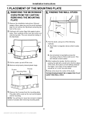
Remove the installation instructions, Exhaust adaptor, filters, glass tray and the small hardware bag. Screws Screws Mounting Plate 1. Stud finder-a magnetic device which locates nails. The center of outcase after removing mounting plate. 8 Draw a line down the center of the oven. 2. Fold back all 4 carton flaps fully against carton sides. Remove and properly discard plastic bags. After locating the stud(s), find the center by probing the wall with a small nail...
Remove the installation instructions, Exhaust adaptor, filters, glass tray and the small hardware bag. Screws Screws Mounting Plate 1. Stud finder-a magnetic device which locates nails. The center of outcase after removing mounting plate. 8 Draw a line down the center of the oven. 2. Fold back all 4 carton flaps fully against carton sides. Remove and properly discard plastic bags. After locating the stud(s), find the center by probing the wall with a small nail...
Installation Instructions
Page 9
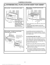
... 30″ space. Tape the Rear Wall Template onto the wall matching the centerline and touching the bottom cabinet frame. Plate position - Remove the decorative trim to install the microwave properly and to make it level. THE MICROWAVE MUST BE LEVEL. For this horizontal line, not touching the cabinet bottom as described in Step D. 9 Installation Instructions C. DETERMINING WALL PLATE LOCATION UNDER YOUR CABINET Plate position - beneath framed recessed cabinet bottom 16-1/2² CL At...
... 30″ space. Tape the Rear Wall Template onto the wall matching the centerline and touching the bottom cabinet frame. Plate position - Remove the decorative trim to install the microwave properly and to make it level. THE MICROWAVE MUST BE LEVEL. For this horizontal line, not touching the cabinet bottom as described in Step D. 9 Installation Instructions C. DETERMINING WALL PLATE LOCATION UNDER YOUR CABINET Plate position - beneath framed recessed cabinet bottom 16-1/2² CL At...
Installation Instructions
Page 12
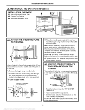
... 3. Installation Instructions A. To use toggle bolts: Mounting Plate Spacing for the power cord to fit through the holes designated to go into the holes in the cabinet bottom. 12 RECIRCULATING (Non-Vented Ductless) INSTALLATION OVERVIEW A1. CAUTION: Be careful to help tighten the bolts. Remove the toggle wings from the wall to avoid pinching fingers between the back of "Rear wall Template" and then the Mounting plate is...
... 3. Installation Instructions A. To use toggle bolts: Mounting Plate Spacing for the power cord to fit through the holes designated to go into the holes in the cabinet bottom. 12 RECIRCULATING (Non-Vented Ductless) INSTALLATION OVERVIEW A1. CAUTION: Be careful to help tighten the bolts. Remove the toggle wings from the wall to avoid pinching fingers between the back of "Rear wall Template" and then the Mounting plate is...

Installation Instructions
Page 13
NOTE: If your cabinet is metal, use handle during installation. NOTE: When mounting the microwave oven, thread power cord through outer top cabinet holes. Rotate front of oven up against the wall and the top cabinet.) 8. Insert 2 self-aligning screws through hole in place against cabinet bottom 3. Install grease filters. Keep it forward, and hook slots at least two full turns after the threads have engaged. (It will be completely...
NOTE: If your cabinet is metal, use handle during installation. NOTE: When mounting the microwave oven, thread power cord through outer top cabinet holes. Rotate front of oven up against the wall and the top cabinet.) 8. Insert 2 self-aligning screws through hole in place against cabinet bottom 3. Install grease filters. Keep it forward, and hook slots at least two full turns after the threads have engaged. (It will be completely...
Installation Instructions
Page 14
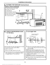
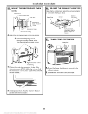
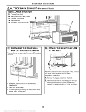
... Ductwork B1. Prepare Top Cabinet B3. CAUTION: Be careful to a wall stud. 1. Pull the plate away from the bolts. 2. Adjust Exhaust Adaptor B7. Mount Microwave Oven B6. At least one wood screw must be used to attach the plate to avoid pinching fingers between the back of "Rear wall Template" and then the Mounting plate is properly centered under the cabinet. Check Damper Operation B5. OUTSIDE TOP EXHAUST (Vertical Duct) INSTALLATION OVERVIEW B1. Installation Instructions B.
... Ductwork B1. Prepare Top Cabinet B3. CAUTION: Be careful to a wall stud. 1. Pull the plate away from the bolts. 2. Adjust Exhaust Adaptor B7. Mount Microwave Oven B6. At least one wood screw must be used to attach the plate to avoid pinching fingers between the back of "Rear wall Template" and then the Mounting plate is properly centered under the cabinet. Check Damper Operation B5. OUTSIDE TOP EXHAUST (Vertical Duct) INSTALLATION OVERVIEW B1. Installation Instructions B.
Installation Instructions
Page 16
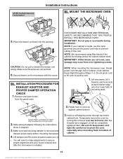
... of mounting plate. Be careful not to pinch the cord, especially when mounting flush to microwave with your cabinet is shipped after being assembled to prevent cutting of top cabinet. MOUNT THE MICROWAVE OVEN 5. INSTALLATION PROCEDURE FOR EXHAUST ADAPTOR AND PROPER DAMPER OPERATION CHECK 1. NOTE: If your house exhaust duct after the threads have engaged. (It will need to make adjustments to keep power cord tight. Insert a self-aligning screw through hole in diagram...
... of mounting plate. Be careful not to pinch the cord, especially when mounting flush to microwave with your cabinet is shipped after being assembled to prevent cutting of top cabinet. MOUNT THE MICROWAVE OVEN 5. INSTALLATION PROCEDURE FOR EXHAUST ADAPTOR AND PROPER DAMPER OPERATION CHECK 1. NOTE: If your house exhaust duct after the threads have engaged. (It will need to make adjustments to keep power cord tight. Insert a self-aligning screw through hole in diagram...
Installation Instructions
Page 17
... Needed B7. Turn two full turns on each screw. Tighten the outer two screws to Depth of the microwave oven. (While tightening screws, hold the microwave oven in place against the wall and the top cabinet.) 1. Installation Instructions B5. Tighten center screw completely. 7. Seal exhaust duct joints using duct tape. 8. Install grease filters. MOUNT THE MICROWAVE OVEN (cont.) Cabinet Front Cabinet Bottom Shelf Filler Block B6. Blower-Plate Damper Back of Microwave Equivalent to the top of Cabinet Recess Self-Aligning Screw Microwave Oven...
... Needed B7. Turn two full turns on each screw. Tighten the outer two screws to Depth of the microwave oven. (While tightening screws, hold the microwave oven in place against the wall and the top cabinet.) 1. Installation Instructions B5. Tighten center screw completely. 7. Seal exhaust duct joints using duct tape. 8. Install grease filters. MOUNT THE MICROWAVE OVEN (cont.) Cabinet Front Cabinet Bottom Shelf Filler Block B6. Blower-Plate Damper Back of Microwave Equivalent to the top of Cabinet Recess Self-Aligning Screw Microwave Oven...
Installation Instructions
Page 18
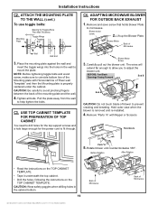
... rear wall. • Cut the opening in the rear wall for outside exhaust. Attach Mounting Plate to ¾ " onto each bolt. 18 Adjust Blower C5. Insert the bolts into the mounting plate through the holes designated to go into drywall and reattach the toggle wings to Wall C3. Installation Instructions C. OUTSIDE BACK EXHAUST (Horizontal Duct) INSTALLATION OVERVIEW C1. Prepare Top Cabinet C4. C2. Prepare Rear Wall C2. PREPARING THE REAR WALL FOR OUTSIDE BACK EXHAUST You need...
... rear wall. • Cut the opening in the rear wall for outside exhaust. Attach Mounting Plate to ¾ " onto each bolt. 18 Adjust Blower C5. Insert the bolts into the mounting plate through the holes designated to go into drywall and reattach the toggle wings to Wall C3. Installation Instructions C. OUTSIDE BACK EXHAUST (Horizontal Duct) INSTALLATION OVERVIEW C1. Prepare Top Cabinet C4. C2. Prepare Rear Wall C2. PREPARING THE REAR WALL FOR OUTSIDE BACK EXHAUST You need...
Installation Instructions
Page 19
... TOP CABINET You need to drill holes for the top support screws and a hole large enough for Toggles More Than Wall Thickness Toggle Wings Toggle Bolt C4. BEFORE: Fan Blade Openings Facing Forward End B End A CAUTION: Do not touch blade of blower to avoid pinching fingers between the back of "Rear wall Template" and then the Mounting plate is removed and re-installed. 4. ATTACH THE MOUNTING PLATE...
... TOP CABINET You need to drill holes for the top support screws and a hole large enough for Toggles More Than Wall Thickness Toggle Wings Toggle Bolt C4. BEFORE: Fan Blade Openings Facing Forward End B End A CAUTION: Do not touch blade of blower to avoid pinching fingers between the back of "Rear wall Template" and then the Mounting plate is removed and re-installed. 4. ATTACH THE MOUNTING PLATE...
Installation Instructions
Page 21
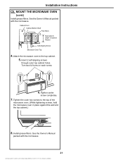
Install grease filters. Installation Instructions C5. Turn two full turns on each screw. 6. Attach the microwave oven to Depth of the microwave oven. (While tightening screws, hold the microwave oven in place against the wall and the top cabinet.) 8. See the Owner's Manual packed with the microwave. Tighten center screw completely. 7. See the Owner's Manual packed with the microwave. 21 Insert 2 self-aligning screws through outer top cabinet holes. Tighten the outer two screws to the top of...
Install grease filters. Installation Instructions C5. Turn two full turns on each screw. 6. Attach the microwave oven to Depth of the microwave oven. (While tightening screws, hold the microwave oven in place against the wall and the top cabinet.) 8. See the Owner's Manual packed with the microwave. Tighten center screw completely. 7. See the Owner's Manual packed with the microwave. 21 Insert 2 self-aligning screws through outer top cabinet holes. Tighten the outer two screws to the top of...
Installation Instructions
Page 22
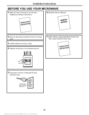
Insure proper ground exists before use 22 Make sure the microwave oven has been installed according to instructions. 6. Replace house fuse or turn breaker back on. 7. Plug power cord into a dedicated 20 amp electrical outlet. Installation Instructions BEFORE YOU USE YOUR MICROWAVE 1. Remove all packing material from the microwave oven. 3. Install turntable and ring in cavity. 4. Read the Owner's Manual. 2. KEEP INSTALLATION INSTRUCTIONS FOR THE LOCAL INSPECTOR'S USE. 5.
Insure proper ground exists before use 22 Make sure the microwave oven has been installed according to instructions. 6. Replace house fuse or turn breaker back on. 7. Plug power cord into a dedicated 20 amp electrical outlet. Installation Instructions BEFORE YOU USE YOUR MICROWAVE 1. Remove all packing material from the microwave oven. 3. Install turntable and ring in cavity. 4. Read the Owner's Manual. 2. KEEP INSTALLATION INSTRUCTIONS FOR THE LOCAL INSPECTOR'S USE. 5.
Specification sheet
Page 1
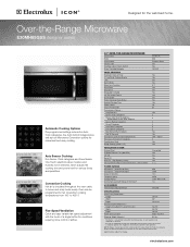
... Exhaust Fan (300 CFM) On / Off Delay Off Auto On - Height Width Depth Overall Exterior Dimensions - Ft. 950 Stainless Steel Yes Yes 13-9/16" PANEL FEATURES Electronic Clock & Timer 2 - Line Scroll Cooking Display Lock Demo Mode More / Less Function Start / Enter Stop / Clear Stoppable Turntable On / Off Sound Control Scroll Speed End of airflow. 30" OVER-THE-RANGE MICROWAVE Oven Cavity Watts Oven Interior Interior Light Cooktop Light w / Touch Control Glass Turntable Diameter 1.6 Cu. Specifications subject to 450° F. Oven can be grounded for various foods...
... Exhaust Fan (300 CFM) On / Off Delay Off Auto On - Height Width Depth Overall Exterior Dimensions - Ft. 950 Stainless Steel Yes Yes 13-9/16" PANEL FEATURES Electronic Clock & Timer 2 - Line Scroll Cooking Display Lock Demo Mode More / Less Function Start / Enter Stop / Clear Stoppable Turntable On / Off Sound Control Scroll Speed End of airflow. 30" OVER-THE-RANGE MICROWAVE Oven Cavity Watts Oven Interior Interior Light Cooktop Light w / Touch Control Glass Turntable Diameter 1.6 Cu. Specifications subject to 450° F. Oven can be grounded for various foods...

Specification sheet
Page 2
...-Range Microwave E30MH65GSS designer series Locate 120V/60Hz grounded outlet inside . • Refer to web for detailed convertible ventilation installation instructions. Can NOT be mounted to improve our products. Note: For planning purposes only. Ducted Option Specifications • For outside ventilation, designed to change specifications or discontinue models without notice. Cabinet MUST be 33" min. Carefully follow top template instructions for outside ventilation only. • Exhaust duct adapter supplied assembled for power cord clearance when installing...
...-Range Microwave E30MH65GSS designer series Locate 120V/60Hz grounded outlet inside . • Refer to web for detailed convertible ventilation installation instructions. Can NOT be mounted to improve our products. Note: For planning purposes only. Ducted Option Specifications • For outside ventilation, designed to change specifications or discontinue models without notice. Cabinet MUST be 33" min. Carefully follow top template instructions for outside ventilation only. • Exhaust duct adapter supplied assembled for power cord clearance when installing...


