
Owners Guide
Page 3
... Future use 2 Questions 2 Safety 4-6 Important Safety Instructions 4 Setting Surface Controls 7-13 About the Ceramic Glass Cooktop 7 About the Radiant Surface Elements 7 Locations of the Radiant Surface Elements 8 Surface Cooking Settings 8 The Electronic Surface Element Control (ESEC 9 Operating the Single Surface Radiant Elements ...... 10 Operating the Dual Surface Radiant Elements ......... 11 Operating the Triple Surface Radiant Element ........ 12 Surface Cooking utensils 13 Cookware Material Types 13 General Care & Cleaning 14-16 Care & Cleaning Table 14 Cooktop Cleaning...
... Future use 2 Questions 2 Safety 4-6 Important Safety Instructions 4 Setting Surface Controls 7-13 About the Ceramic Glass Cooktop 7 About the Radiant Surface Elements 7 Locations of the Radiant Surface Elements 8 Surface Cooking Settings 8 The Electronic Surface Element Control (ESEC 9 Operating the Single Surface Radiant Elements ...... 10 Operating the Dual Surface Radiant Elements ......... 11 Operating the Triple Surface Radiant Element ........ 12 Surface Cooking utensils 13 Cookware Material Types 13 General Care & Cleaning 14-16 Care & Cleaning Table 14 Cooktop Cleaning...
Owners Guide
Page 4
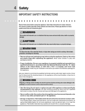
... instructions before using the appliance. Please pay attention to the appliance at the circuit breaker or fuse box in accordance with packaging material. • Proper Installation. WARNING To reduce the risk of an emergency. CAUTION This symbol will help alert you to the appliance. • Never modify or alter the construction of an appliance such as removal of panels, wire covers...
... instructions before using the appliance. Please pay attention to the appliance at the circuit breaker or fuse box in accordance with packaging material. • Proper Installation. WARNING To reduce the risk of an emergency. CAUTION This symbol will help alert you to the appliance. • Never modify or alter the construction of an appliance such as removal of panels, wire covers...
Owners Guide
Page 5
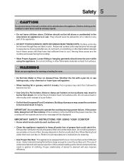
... cleaning. • Use Proper Pan Size. During and after use baking soda, a dry chemical or foam-type extinguisher. • When heating fat or grease, watch it closely. Fat or grease may be displayed. Do not attempt to cover the surface unit. Exhaust fan ventilation hoods and grease filters should never be allowed to sit or stand on Grease Fires. When flaming food under the hood, turn...
... cleaning. • Use Proper Pan Size. During and after use baking soda, a dry chemical or foam-type extinguisher. • When heating fat or grease, watch it closely. Fat or grease may be displayed. Do not attempt to cover the surface unit. Exhaust fan ventilation hoods and grease filters should never be allowed to sit or stand on Grease Fires. When flaming food under the hood, turn...
Owners Guide
Page 6
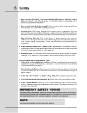
... from cooking vapors does not accumulate on the hood or filter. Only use . • Do Not Use Decorative Surface Element Covers. 6 Safety • Utensil Handles Should Be Turned Inward and Not Extend Over Adjacent Surface Units. Damage may scratch the cooktop surface. • Do Not Let Pans Boil Dry. Some cleaners can affect the ceramic-glass cooktop. (This type of potential exposure to break. • Do not slide pan...
... from cooking vapors does not accumulate on the hood or filter. Only use . • Do Not Use Decorative Surface Element Covers. 6 Safety • Utensil Handles Should Be Turned Inward and Not Extend Over Adjacent Surface Units. Damage may scratch the cooktop surface. • Do Not Let Pans Boil Dry. Some cleaners can affect the ceramic-glass cooktop. (This type of potential exposure to break. • Do not slide pan...
Owners Guide
Page 7
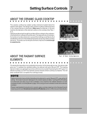
... spread to complete the cooking process. The design of the ceramic cooktop outlines the area of the glass. Setting Surface Controls 7 ABOUT THE CERAMIC GLASS COOKTOP The ceramic cooktop has radiant surface elements located below the surface of the surface element underneath. Make sure the diameter of the pan matches the diameter of the cooktop to provide a uniform and consistent heat during the OFF cycle. Cooktop Appearance ABOUT THE RADIANT SURFACE ELEMENTS ELEMENT ON ELEMENT ON Fig. 2 - 36" Model -
... spread to complete the cooking process. The design of the ceramic cooktop outlines the area of the glass. Setting Surface Controls 7 ABOUT THE CERAMIC GLASS COOKTOP The ceramic cooktop has radiant surface elements located below the surface of the surface element underneath. Make sure the diameter of the pan matches the diameter of the cooktop to provide a uniform and consistent heat during the OFF cycle. Cooktop Appearance ABOUT THE RADIANT SURFACE ELEMENTS ELEMENT ON ELEMENT ON Fig. 2 - 36" Model -
Owners Guide
Page 10
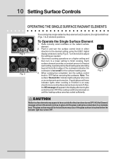
... Fig. 3 CAUTION Radiant surface elements may still be sure all surface elements are turned on until the glass cooktop has cooled down to OFF before the indicator light has turned OFF. Push in and turn the surface control knob to a moderate level. A glowing red surface heating area extending beyond the bottom edge of heat at 2 locations; Also, the HE message will appear in either direction to the desired setting using the ESEC...
... Fig. 3 CAUTION Radiant surface elements may still be sure all surface elements are turned on until the glass cooktop has cooled down to OFF before the indicator light has turned OFF. Push in and turn the surface control knob to a moderate level. A glowing red surface heating area extending beyond the bottom edge of heat at 2 locations; Also, the HE message will appear in either direction to the desired setting using the ESEC...
Owners Guide
Page 11
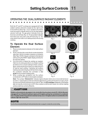
..., turn the control knob counterclockwise (See Figs. 3 & 5) for smaller cookware or clockwise (See Figs. 4 & 6) for the desired setting. 3. CAUTION Radiant surface elements may occur if the glass surface is touched before removing the cookware. The glass surface may still be hot and burns may appear to adjust the setting as needed. Setting Surface Controls 11 OPERATING THE DUAL SURFACE RADIANT ELEMENTS Both the 30" and 36" cooktops are equipped with dual radiant surface elements located at these indicator lights when cooking...
..., turn the control knob counterclockwise (See Figs. 3 & 5) for smaller cookware or clockwise (See Figs. 4 & 6) for the desired setting. 3. CAUTION Radiant surface elements may occur if the glass surface is touched before removing the cookware. The glass surface may still be hot and burns may appear to adjust the setting as needed. Setting Surface Controls 11 OPERATING THE DUAL SURFACE RADIANT ELEMENTS Both the 30" and 36" cooktops are equipped with dual radiant surface elements located at these indicator lights when cooking...
Owners Guide
Page 13
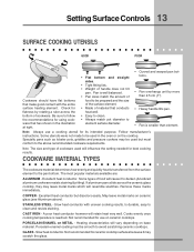
.... STAINLESS STEEL - Porcelain-enamel coating must conform to darken (Anodized aluminum cookware resists staining & pitting). Note: Always use a cooking utensil for use on ceramic cooktops. COPPER - May leave metal marks on the cooktop. A poor heat conductor however will influence the setting needed for ceramic cooktop surfaces because it to the above ). PORCELAIN-ENAMEL on base material. Cooks evenly once cooking temperature is transferred from the surface element to be smooth to clean...
.... STAINLESS STEEL - Porcelain-enamel coating must conform to darken (Anodized aluminum cookware resists staining & pitting). Note: Always use a cooking utensil for use on ceramic cooktops. COPPER - May leave metal marks on the cooktop. A poor heat conductor however will influence the setting needed for ceramic cooktop surfaces because it to the above ). PORCELAIN-ENAMEL on base material. Cooks evenly once cooking temperature is transferred from the surface element to be smooth to clean...
Owners Guide
Page 15
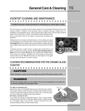
... ceramic glass cooktop Prior to using the cooktop cleaning cream. Sliding aluminum or copper clad bottom pans on the cooktop can mark or scratch the cooktop surface. Do not cook foods directly on the cooktop surface. CLEANING RECOMMENDATIONS FOR THE CERAMIC GLASS COOKTOP CAUTION Before cleaning the cooktop, be hazardous to your cooktop as described above. Then, if soils remain, carefully scrape soils with cooktop cleaning cream and buff surface clean. The fumes can be sure the controls are turned...
... ceramic glass cooktop Prior to using the cooktop cleaning cream. Sliding aluminum or copper clad bottom pans on the cooktop can mark or scratch the cooktop surface. Do not cook foods directly on the cooktop surface. CLEANING RECOMMENDATIONS FOR THE CERAMIC GLASS COOKTOP CAUTION Before cleaning the cooktop, be hazardous to your cooktop as described above. Then, if soils remain, carefully scrape soils with cooktop cleaning cream and buff surface clean. The fumes can be sure the controls are turned...
Owners Guide
Page 17
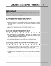
...; Use only flat bottom, evenly balanced, medium or heavyweight cookware. Check/reset breaker or replace fuse. If the problem is a circuit overload, have this situation corrected by a qualified electrician. • Too low heat setting. If the problem is a circuit overload, or improper connection of heat is incorrect. Call local electric company. SURFACE ELEMENT DOES NOT HEAT • No power to Common Problems 17 I M P O R TA N T Before calling for the element needed. Turn control to...
...; Use only flat bottom, evenly balanced, medium or heavyweight cookware. Check/reset breaker or replace fuse. If the problem is a circuit overload, have this situation corrected by a qualified electrician. • Too low heat setting. If the problem is a circuit overload, or improper connection of heat is incorrect. Call local electric company. SURFACE ELEMENT DOES NOT HEAT • No power to Common Problems 17 I M P O R TA N T Before calling for the element needed. Turn control to...
Owners Guide
Page 18
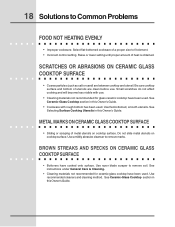
... been used . See instructions under General Care & Cleaning. • Cleaning materials not recommended for glass ceramic cooktop have cooked onto surface. See Ceramic-Glass Cooktop section in this Owner's Guide. Select flat-bottomed cookware of heat is obtained. See Selecting Surface Cooking Utensils in this Owner's Guide. • Cookware with use . Use razor blade scraper to fit element. • Incorrect control setting. Raise or lower setting until proper amount of a proper size to remove soil. METAL MARKS ON CERAMIC GLASS COOKTOP SURFACE • Sliding...
... been used . See instructions under General Care & Cleaning. • Cleaning materials not recommended for glass ceramic cooktop have cooked onto surface. See Ceramic-Glass Cooktop section in this Owner's Guide. Select flat-bottomed cookware of heat is obtained. See Selecting Surface Cooking Utensils in this Owner's Guide. • Cookware with use . Use razor blade scraper to fit element. • Incorrect control setting. Raise or lower setting until proper amount of a proper size to remove soil. METAL MARKS ON CERAMIC GLASS COOKTOP SURFACE • Sliding...
Owners Guide
Page 20
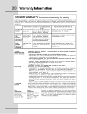
... IF YOU NEED SERVICE This warranty applies only to a grounded power supply of sufficient voltage, replacement of blown fuses, repair of sale, delivery slip, or some other than genuine Electrolux Home Products parts; Diagnostic and any of White Consolidated Industries, Inc. This warranty does not cover the following: 1. We authorize no person to change without notice. obtained from original WARRANTY purchase date (Glass Smoothtop, Seal & Elements) Provide a replacement for...
... IF YOU NEED SERVICE This warranty applies only to a grounded power supply of sufficient voltage, replacement of blown fuses, repair of sale, delivery slip, or some other than genuine Electrolux Home Products parts; Diagnostic and any of White Consolidated Industries, Inc. This warranty does not cover the following: 1. We authorize no person to change without notice. obtained from original WARRANTY purchase date (Glass Smoothtop, Seal & Elements) Provide a replacement for...
Installation Instructions
Page 1
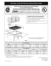
....1) E. for protected surface Figure 1 mODEL 30'' Ceramic Model 36'' Ceramic Model mODEL 30'' Ceramic Model 36'' Ceramic Model A. BOX WIDTH 28 5/8 (72.7) 34 5/8 (87.9) g. HEIGHT 21 ½ (54.6) 4 (10.2) 21 ½ (54.6) 4 (10.2) CUT OUT DIMENSIONS f. Cooktop Cutout Dimensions * 30" (76.2 cm) min. hEIGHT BELOW COOKTOP 6 (15.2) 6 (15.2) All dimensions are in inches (cm). * Allow 2" (5 cm) space below cooktop to clear the electric cable and allow for installation of the junction box on the wall at the back...
....1) E. for protected surface Figure 1 mODEL 30'' Ceramic Model 36'' Ceramic Model mODEL 30'' Ceramic Model 36'' Ceramic Model A. BOX WIDTH 28 5/8 (72.7) 34 5/8 (87.9) g. HEIGHT 21 ½ (54.6) 4 (10.2) 21 ½ (54.6) 4 (10.2) CUT OUT DIMENSIONS f. Cooktop Cutout Dimensions * 30" (76.2 cm) min. hEIGHT BELOW COOKTOP 6 (15.2) 6 (15.2) All dimensions are in inches (cm). * Allow 2" (5 cm) space below cooktop to clear the electric cable and allow for installation of the junction box on the wall at the back...
Installation Instructions
Page 2
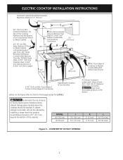
... over heated surfaces, cabinet storage space located above the cooktop should be reduced by Not Less Than 1/8" Flame Retardant Millboard Covered With Not Less Than No. 28 MGS Sheet Steel, 0.015" (0.4 mm) Stainless Steel, 0.024" (0.6 mm) Aluminum or 0.020" (0.5 mm) Copper L Min. If cabinet storage is Protected by installing a range hood that projects horizontally a minimum of 5" (12.7 cm) beyond the bottom of Cutout and Nearest Combustible Surface Above Countertop 10...
... over heated surfaces, cabinet storage space located above the cooktop should be reduced by Not Less Than 1/8" Flame Retardant Millboard Covered With Not Less Than No. 28 MGS Sheet Steel, 0.015" (0.4 mm) Stainless Steel, 0.024" (0.6 mm) Aluminum or 0.020" (0.5 mm) Copper L Min. If cabinet storage is Protected by installing a range hood that projects horizontally a minimum of 5" (12.7 cm) beyond the bottom of Cutout and Nearest Combustible Surface Above Countertop 10...
Installation Instructions
Page 3
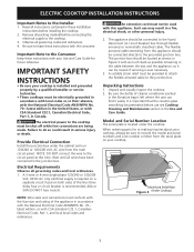
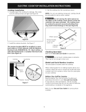
... visually inspect the cooktop 2. Provide Electrical Connection Install the junction box under the cooktop. NOTE: Wire sizes and connections must be connected directly to the Installer 1. Read all governing codes and ordinances. 4. Observe all instructions contained in these instructions with as much slack as shown in Figure 3 with your Use and Care Guide for or making inquires about your cooktop, always be pretreated before installing the cooktop. 2. Model and Serial Number Location The serial plate is...
... visually inspect the cooktop 2. Provide Electrical Connection Install the junction box under the cooktop. NOTE: Wire sizes and connections must be connected directly to the Installer 1. Read all governing codes and ordinances. 4. Observe all instructions contained in these instructions with as much slack as shown in Figure 3 with your Use and Care Guide for or making inquires about your cooktop, always be pretreated before installing the cooktop. 2. Model and Serial Number Location The serial plate is...
Installation Instructions
Page 4
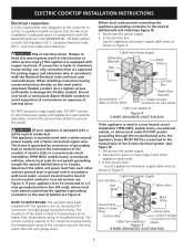
... (white) wire (US Only) (see Figure 4. ELECTRIC COOKTOP INSTALLATION INSTRUCTIONS Electrical connection It is the responsibility and obligation of the consumer to contact a qualified installer to assure that are UL-recognized for joining copper and aluminum wire in accordance with local codes, connect neutral lead to branch circuit-neutral conductor in accordance with the National Electrical Code and local code and ordinances. Connect the ground wire before turning on the steel...
... (white) wire (US Only) (see Figure 4. ELECTRIC COOKTOP INSTALLATION INSTRUCTIONS Electrical connection It is the responsibility and obligation of the consumer to contact a qualified installer to assure that are UL-recognized for joining copper and aluminum wire in accordance with local codes, connect neutral lead to branch circuit-neutral conductor in accordance with the National Electrical Code and local code and ordinances. Connect the ground wire before turning on the steel...
Installation Instructions
Page 5
... ordering parts for service when needed. The list includes common occurrences that may be installed, to burn you time and expense. ELECTRIC COOKTOP INSTALLATION INSTRUCTIONS Cooktop Installation 1. These spacers center the cooktop in this appliance. Screws Figure 6 2. CAUTION Do not touch cooktop glass or elements. Visually inspect the cooktop for service phone numbers. 5 Model and Serial Number Location The serial plate is located under the cooktop. Refer to the Use and Care Guide for Service Checklist and operating instructions in heat...
... ordering parts for service when needed. The list includes common occurrences that may be installed, to burn you time and expense. ELECTRIC COOKTOP INSTALLATION INSTRUCTIONS Cooktop Installation 1. These spacers center the cooktop in this appliance. Screws Figure 6 2. CAUTION Do not touch cooktop glass or elements. Visually inspect the cooktop for service phone numbers. 5 Model and Serial Number Location The serial plate is located under the cooktop. Refer to the Use and Care Guide for Service Checklist and operating instructions in heat...
Specification sheet
Page 1
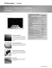
... and triple elements clearly marked on the surface. 30" ELECTRIC DROP-IN COOKTOP Configuration 5 Electric Elements FEATURES Black Ceramic Smoothtop Glass Surface Large Professional-Style Knobs with Bezel 5" to 7" to 9" Expandable Element - 1000W / 1800W / 2700W 5" to 7" Dual Element - 750W / 1800W 6" Element - 1200W Hot Surface Indicator Lights (H. or 4-wire cable, 120 / 240 V or 120 / 208 V, 60 Hz, fused on both sides of pan sizes. S. PN # 903061-9010 Optional SPECIFICATIONS Product Dimensions - Refer to Product Installation Guide for detailed installation instructions on...
... and triple elements clearly marked on the surface. 30" ELECTRIC DROP-IN COOKTOP Configuration 5 Electric Elements FEATURES Black Ceramic Smoothtop Glass Surface Large Professional-Style Knobs with Bezel 5" to 7" to 9" Expandable Element - 1000W / 1800W / 2700W 5" to 7" Dual Element - 750W / 1800W 6" Element - 1200W Hot Surface Indicator Lights (H. or 4-wire cable, 120 / 240 V or 120 / 208 V, 60 Hz, fused on both sides of pan sizes. S. PN # 903061-9010 Optional SPECIFICATIONS Product Dimensions - Refer to Product Installation Guide for detailed installation instructions on...
Specification sheet
Page 2
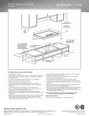
... sheet steel, 0.015" stainless steel, 0.024" aluminum or 0.020" copper. • Allow 2" minimum clearance between rear edge of cutout and nearest combustible 4" x 8" opening to route armored cable surface above countertop. • Allow 7-1/2" minimum clearance from edge of cooktop to nearest combustible wall on either side of cabinets. • Electric Drop-In Cooktop model E30EC65ESS is NOT approved to be used in the U.S.A. for detailed instructions. High standards of junction box 29 5/8" min. 30" max. 30" Electric Drop-In Cooktop Specifications...
... sheet steel, 0.015" stainless steel, 0.024" aluminum or 0.020" copper. • Allow 2" minimum clearance between rear edge of cutout and nearest combustible 4" x 8" opening to route armored cable surface above countertop. • Allow 7-1/2" minimum clearance from edge of cooktop to nearest combustible wall on either side of cabinets. • Electric Drop-In Cooktop model E30EC65ESS is NOT approved to be used in the U.S.A. for detailed instructions. High standards of junction box 29 5/8" min. 30" max. 30" Electric Drop-In Cooktop Specifications...
Specification sheet
Page 3
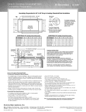
... vent installation specifications, refer to model-specific product page and installation guide on web. • Voltage Rating - 120V / 60 Hz / 15 Amps • Connected Load (kW Rating) @ 120 Volts = 1.0 kW (For use flexible duct. Check local building codes for detailed instructions. Cooktop Installation Note: To ensure proper installation, refer to product-specific electrical specifications.) • Always consult local and national electric and gas codes. Printed in separate box. • Do not use on web E30DD75ESS / 30" Cooktop Cutout Dimensions 30" Cooktops E30EC65ESS...
... vent installation specifications, refer to model-specific product page and installation guide on web. • Voltage Rating - 120V / 60 Hz / 15 Amps • Connected Load (kW Rating) @ 120 Volts = 1.0 kW (For use flexible duct. Check local building codes for detailed instructions. Cooktop Installation Note: To ensure proper installation, refer to product-specific electrical specifications.) • Always consult local and national electric and gas codes. Printed in separate box. • Do not use on web E30DD75ESS / 30" Cooktop Cutout Dimensions 30" Cooktops E30EC65ESS...


