
User Guide
Page 4
... 25 Enter BIOS Setup 26 Main Menu...26 Standard BIOS Features Menu 28 System Time / System Date 29 Advanced BIOS Features 29 IDE Configuration 30 Boot Settings Configuration 30 AHCI Configuration 30 Intel VT-d Configuration 31 USB Configuration 31 Advanced Chipset Features 31 North Bridge Configuration 31 PCI Express Configuration 32...
... 25 Enter BIOS Setup 26 Main Menu...26 Standard BIOS Features Menu 28 System Time / System Date 29 Advanced BIOS Features 29 IDE Configuration 30 Boot Settings Configuration 30 AHCI Configuration 30 Intel VT-d Configuration 31 USB Configuration 31 Advanced Chipset Features 31 North Bridge Configuration 31 PCI Express Configuration 32...
User Guide
Page 5
EVGA P55 LE Motherboard Allocate IRQ to PCI VGA 34 Palette Snooping 34 PCI IDE BusMaster 34 OffBoard PCI/ISA IDE Card 34 IRQ Settings ...34 Boot Configuration Features 35 Boot Device Priority 35 Hard Disk Drives 35 CD/DVD Drives 36 Power Management Features 36 ACPI Configuration 36 SLP_S4# Min. Assertion Width 36 Restore on... Control Menu 38 Memory Configure 38 CPU Configuration 38 Installing Drivers and Software 39 Windows XP/Vista/7 Driver Installation 39 Appendix A. POST Codes for the EVGA P55 LE Motherboard 40
EVGA P55 LE Motherboard Allocate IRQ to PCI VGA 34 Palette Snooping 34 PCI IDE BusMaster 34 OffBoard PCI/ISA IDE Card 34 IRQ Settings ...34 Boot Configuration Features 35 Boot Device Priority 35 Hard Disk Drives 35 CD/DVD Drives 36 Power Management Features 36 ACPI Configuration 36 SLP_S4# Min. Assertion Width 36 Restore on... Control Menu 38 Memory Configure 38 CPU Configuration 38 Installing Drivers and Software 39 Windows XP/Vista/7 Driver Installation 39 Appendix A. POST Codes for the EVGA P55 LE Motherboard 40

User Guide
Page 6
Advanced Chipset Features 31 Figure 6. PCI/PNP Resource Management 33 Figure 7. Boot Configuration Features 35 Figure 8. Hardware Health Configure 37 Figure 10. List of Figures Figure 1. Advanced BIOS Features 30 Figure 5. Frequency/Voltage Control 38 PW1 Motherboard Connector 16 Figure 2. CMOS Setup Utility Main Menu 27 Figure 3. Standard BIOS Features Menu 28 Figure 4. Power Management Features 36 Figure 9.
Advanced Chipset Features 31 Figure 6. PCI/PNP Resource Management 33 Figure 7. Boot Configuration Features 35 Figure 8. Hardware Health Configure 37 Figure 10. List of Figures Figure 1. Advanced BIOS Features 30 Figure 5. Frequency/Voltage Control 38 PW1 Motherboard Connector 16 Figure 2. CMOS Setup Utility Main Menu 27 Figure 3. Standard BIOS Features Menu 28 Figure 4. Power Management Features 36 Figure 9.
User Guide
Page 24
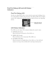
... Port Debug LED and LED Status Indicators Post Port Debug LED Provides two-digit POST codes to show why the system may be failing to boot. It is receiving constant power. Debug LED with CPU Temperature Monitor LED Status Indicators The LEDs near the 24pin ATX connector indicate the system's status...
... Port Debug LED and LED Status Indicators Post Port Debug LED Provides two-digit POST codes to show why the system may be failing to boot. It is receiving constant power. Debug LED with CPU Temperature Monitor LED Status Indicators The LEDs near the 24pin ATX connector indicate the system's status...

User Guide
Page 25
This section includes the following information: Enter BIOS Setup Main Menu Standard BIOS Features Advanced BIOS Features Advanced Chipset Features PCI/PnP Resource Management Boot Configuration Features Power Management Features Hardware Health Configure Frequency/Voltage Control Configuring the BIOS This section discusses how to change the system settings through the BIOS Setup menus. Descriptions of the BIOS parameters are also provided.
This section includes the following information: Enter BIOS Setup Main Menu Standard BIOS Features Advanced BIOS Features Advanced Chipset Features PCI/PnP Resource Management Boot Configuration Features Power Management Features Hardware Health Configure Frequency/Voltage Control Configuring the BIOS This section discusses how to change the system settings through the BIOS Setup menus. Descriptions of the BIOS parameters are also provided.
User Guide
Page 26
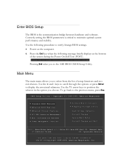
... Setup Utility - Copyright (C) 1985-2005, American Megatrends Standard BIOS Features Advanced BIOS Features Advanced Chipset Features PCI/PNP Resource Management Boot Configuration Features Power Management Features Hardware Health Configure Frequency/Voltage Control Load Optimal Defaults Discard Changes Save & Exit Setup Discard Changes and...
... Setup Utility - Copyright (C) 1985-2005, American Megatrends Standard BIOS Features Advanced BIOS Features Advanced Chipset Features PCI/PNP Resource Management Boot Configuration Features Power Management Features Hardware Health Configure Frequency/Voltage Control Load Optimal Defaults Discard Changes Save & Exit Setup Discard Changes and...
User Guide
Page 27
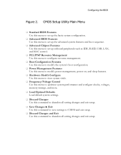
...this menu to set up the basic system configuration. Advanced BIOS Features Use this menu to set up the advanced system features and boot sequence. Advanced Chipset Features Use this menu to set up onboard peripherals such as IDE, RAID, USB, LAN, and MAC control.... PCI/PNP Resource Management Use this menu to configure resource management. Boot Configuration Features Use this menu to modify the system's boot configuration. Power Management Features Use this menu to modify power management, power on, and sleep features. ...
...this menu to set up the basic system configuration. Advanced BIOS Features Use this menu to set up the advanced system features and boot sequence. Advanced Chipset Features Use this menu to set up onboard peripherals such as IDE, RAID, USB, LAN, and MAC control.... PCI/PNP Resource Management Use this menu to configure resource management. Boot Configuration Features Use this menu to modify the system's boot configuration. Power Management Features Use this menu to modify power management, power on, and sleep features. ...

User Guide
Page 30
... more. Advanced Settings WARNING: Setting wrong values in below sections may cause system to use AHCI mode for new system installations. Boot Settings Configuration Use this to configure your storage drivers and to configure various system options, such as S.M.A.R.T. Please note for Windows ...Vista / Windows 7, it is recommended to malfunction. IDE Configuration [Press Enter] Boot Settings Configuration[Press Enter] AHCI Configuration [Press Enter] USB Configuration [Press Enter] Help Item Main Level Select Removable...
... more. Advanced Settings WARNING: Setting wrong values in below sections may cause system to use AHCI mode for new system installations. Boot Settings Configuration Use this to configure your storage drivers and to configure various system options, such as S.M.A.R.T. Please note for Windows ...Vista / Windows 7, it is recommended to malfunction. IDE Configuration [Press Enter] Boot Settings Configuration[Press Enter] AHCI Configuration [Press Enter] USB Configuration [Press Enter] Help Item Main Level Select Removable...
User Guide
Page 31
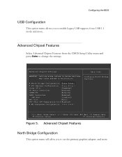
.... North Bridge Configuration [Press Enter] PCI Express Configuration [Press Enter] Intel VT-d [Disabled] HD Audio Controller [Enabled] IEEE1394 [Enabled] LAN1 Controller [Enabled] LAN Boot [Disabled] PE1 Slot [Auto] P80 Show CPU Temperature Slot[Enabled] ME Subsystem Configuration [Press Enter] Help Item Configure North Bridge features. Advanced Chipset Features...
.... North Bridge Configuration [Press Enter] PCI Express Configuration [Press Enter] Intel VT-d [Disabled] HD Audio Controller [Enabled] IEEE1394 [Enabled] LAN1 Controller [Enabled] LAN Boot [Disabled] PE1 Slot [Auto] P80 Show CPU Temperature Slot[Enabled] ME Subsystem Configuration [Press Enter] Help Item Configure North Bridge features. Advanced Chipset Features...

User Guide
Page 33
Advanced PCI/PnP Settings WARNING: Setting wrong values in units of [No] is default. Help Item Clear NVRAM during System Boot. Plug & Play O/S This function sets whether the O/S or BIOS configures Plug and Play devices. A setting of PCI clocks. PCI Latency Timer This ...function sets the value in below sections may cause system to malfunction. PCI/PNP Resource Management Clear NVRAM This function clears the NVRAM during System Boot. Clear NVRAM Plug & Play O/S PCI Latency Timer Allocate IRQ to display the advanced settings. PCI/PNP Resource Management Select PCI/PNP Resource ...
Advanced PCI/PnP Settings WARNING: Setting wrong values in units of [No] is default. Help Item Clear NVRAM during System Boot. Plug & Play O/S This function sets whether the O/S or BIOS configures Plug and Play devices. A setting of PCI clocks. PCI Latency Timer This ...function sets the value in below sections may cause system to malfunction. PCI/PNP Resource Management Clear NVRAM This function clears the NVRAM during System Boot. Clear NVRAM Plug & Play O/S PCI Latency Timer Allocate IRQ to display the advanced settings. PCI/PNP Resource Management Select PCI/PNP Resource ...

User Guide
Page 35
... Priority Hard Disk Drives CD/DVD Drives [Press Enter] [Press Enter] [Press Enter] Help Item Specifies the Boot Device Priority sequence. Move Enter:Select +/-/:Value F10:Save ESC:Exit F1:General Help F5:Previous Values F7:Optimized Defaults Move Enter:Select +/-/PU/PD:...
... Priority Hard Disk Drives CD/DVD Drives [Press Enter] [Press Enter] [Press Enter] Help Item Specifies the Boot Device Priority sequence. Move Enter:Select +/-/:Value F10:Save ESC:Exit F1:General Help F5:Previous Values F7:Optimized Defaults Move Enter:Select +/-/PU/PD:...

User Guide
Page 36
Assertion Width [4 to display the settings. SLP_S4# Min. Assertion Width This function allows adjustment of the CD/DVD boot priority sequence. Power Management Features ACPI Configuration [Press Enter] SLP_S4# Min. Move Enter:Select +/-/:Value F10:Save ESC:Exit F1:General Help F5:Previous ...
Assertion Width [4 to display the settings. SLP_S4# Min. Assertion Width This function allows adjustment of the CD/DVD boot priority sequence. Power Management Features ACPI Configuration [Press Enter] SLP_S4# Min. Move Enter:Select +/-/:Value F10:Save ESC:Exit F1:General Help F5:Previous ...

User Guide
Page 40
... calling pointer Primary initialization of CPU Secondary initialization of chipset registers POST Codes for the EVGA P55 LE Motherboard This section provides the AMI POST Codes (Table 6) for the EVGA P55 LE Motherboard during system boot up application processors Re-enable cache for boot strap processor Early CPU initialization exit Initialize keyboard controller Detect Mouse Detect Keyboard Test...
... calling pointer Primary initialization of CPU Secondary initialization of chipset registers POST Codes for the EVGA P55 LE Motherboard This section provides the AMI POST Codes (Table 6) for the EVGA P55 LE Motherboard during system boot up application processors Re-enable cache for boot strap processor Early CPU initialization exit Initialize keyboard controller Detect Mouse Detect Keyboard Test...

User Guide
Page 41
...vector Uncompress and initialize BIOS module Initialize devices primary Initialize devices secondary Initialize output devices Allocate memory for ADM module Initialize silent boot module Display sign-on message Initialize USB controller Initialize DMAC-1 & DMAC-2 Initialize real time clock Test system memory Initialization of... of chipset registers Build ACPI tables Program peripheral parameters Initialize system management interrupt Prepare for system boot Initialize IRQ routing table Display boot option popup Display system configuration screen Wait for user input at configuration display
...vector Uncompress and initialize BIOS module Initialize devices primary Initialize devices secondary Initialize output devices Allocate memory for ADM module Initialize silent boot module Display sign-on message Initialize USB controller Initialize DMAC-1 & DMAC-2 Initialize real time clock Test system memory Initialization of... of chipset registers Build ACPI tables Program peripheral parameters Initialize system management interrupt Prepare for system boot Initialize IRQ routing table Display boot option popup Display system configuration screen Wait for user input at configuration display

User Guide
Page 42
... AA AB AC B1 00 (can vary) Description Uninstall POST vector Prepare BBS for Int 19 boot End of POST initialization Save system context for ACPI Pass control to OS Show CPU Temp (if enabled) EVGA Glossary of Terms ACPI - Compact Disc Read-Only Memory CMOS - Floppy Disk Controller FSB - Central Processing...
... AA AB AC B1 00 (can vary) Description Uninstall POST vector Prepare BBS for Int 19 boot End of POST initialization Save system context for ACPI Pass control to OS Show CPU Temp (if enabled) EVGA Glossary of Terms ACPI - Compact Disc Read-Only Memory CMOS - Floppy Disk Controller FSB - Central Processing...
