
PDF Spec Sheet
Page 1
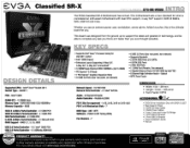
... EVGA Classified SR-X Motherboard has arrived. Intel° Xeon® Socket 2011 Socket Type - For more . RAID 0, 1, 5, 10, JBOD Network Speed - 10/100/1000 Network Ports/Controller - 2 / Intel® 82574L Audio - 8 Channel HD Audio Audio Controller - Realtek ALC898 PCI-E Slot Arrangement - 1x16, 2x16, 3x16 or 2x16+2x8 PCI-E x16 Mechanical Slots - 7 BIOS Type - LGA2011 PCH - CV3A Classified SR-X 270-SE-W888 -INTRO 1 CV3A. Whether you . EVGA E-LEET Tuning Utility Fan Headers - 7 DIMENSIONS I I I I I I I I /O Panel • 6 SATA 3G Data Cables • 3 SATA Power Cables...
... EVGA Classified SR-X Motherboard has arrived. Intel° Xeon® Socket 2011 Socket Type - For more . RAID 0, 1, 5, 10, JBOD Network Speed - 10/100/1000 Network Ports/Controller - 2 / Intel® 82574L Audio - 8 Channel HD Audio Audio Controller - Realtek ALC898 PCI-E Slot Arrangement - 1x16, 2x16, 3x16 or 2x16+2x8 PCI-E x16 Mechanical Slots - 7 BIOS Type - LGA2011 PCH - CV3A Classified SR-X 270-SE-W888 -INTRO 1 CV3A. Whether you . EVGA E-LEET Tuning Utility Fan Headers - 7 DIMENSIONS I I I I I I I I /O Panel • 6 SATA 3G Data Cables • 3 SATA Power Cables...
PDF Spec Sheet
Page 2
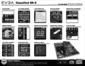
CPU I • PhysX - AI. For more details please visit www.evga.com/warranty I Memo, MommaI Ora*. Q. 0. Core Speed 1 3900 0 laTIE MulvIer Hno,2.33 IOC 0 IIHZ Data 1-E, WEI Leve.2 Kflyles Cores Threads TRIPLE BIOS SUPPORT Use 3 separate profiles! 15105_,SEL 1 ONBOARD MINI SAS CONNECTORS Connect up to 8 SATA or SAS devices •• ONBOARD BLUETOOTH Wireless input and data connection EZ VOLTAGE READ POINTS Easy read dedicated read...
CPU I • PhysX - AI. For more details please visit www.evga.com/warranty I Memo, MommaI Ora*. Q. 0. Core Speed 1 3900 0 laTIE MulvIer Hno,2.33 IOC 0 IIHZ Data 1-E, WEI Leve.2 Kflyles Cores Threads TRIPLE BIOS SUPPORT Use 3 separate profiles! 15105_,SEL 1 ONBOARD MINI SAS CONNECTORS Connect up to 8 SATA or SAS devices •• ONBOARD BLUETOOTH Wireless input and data connection EZ VOLTAGE READ POINTS Easy read dedicated read...
User Guide
Page 2
EVGA Classified SR-X Motherboard Table of Contents Before You Begin 4 Motherboard Specifications 5 Unpacking and Parts Descriptions 6-7 Equipment ...8-9 Hardware Installation 10 Installing the CPU 11-12 Installing the Cooling Device 13 Installing DIMMs 13 Installing the Motherboard 14 Motherboard I/O Panel 14 Securing the Motherboard into the Chassis 15 Connecting Cables and Setting Switches 16 24-pin ATX Power (PW1 16 8-pin ATX 12V Power (PW12-P0-1, PW12-P1-1 17 Connecting Serial ATA Cables 18 Front Panel Header 19 USB Headers ...20 Audio Header...21 Fan Connections 22 ...
EVGA Classified SR-X Motherboard Table of Contents Before You Begin 4 Motherboard Specifications 5 Unpacking and Parts Descriptions 6-7 Equipment ...8-9 Hardware Installation 10 Installing the CPU 11-12 Installing the Cooling Device 13 Installing DIMMs 13 Installing the Motherboard 14 Motherboard I/O Panel 14 Securing the Motherboard into the Chassis 15 Connecting Cables and Setting Switches 16 24-pin ATX Power (PW1 16 8-pin ATX 12V Power (PW12-P0-1, PW12-P1-1 17 Connecting Serial ATA Cables 18 Front Panel Header 19 USB Headers ...20 Audio Header...21 Fan Connections 22 ...

User Guide
Page 3
EVGA Classified SR-X Motherboard Onboard Buttons 25 Post Port Debug LED and LED Status Indicators 26 PCIE-E Disable Swtiches 27 CPU1 Disable Swtiches 28 DIMM Disable Swtiches 29 Voltage Measure Point 30 Installing Drivers and Software 31 POST Codes 32-33 EVGA Glossary of Terms 34-36 Compliance Information 37 3
EVGA Classified SR-X Motherboard Onboard Buttons 25 Post Port Debug LED and LED Status Indicators 26 PCIE-E Disable Swtiches 27 CPU1 Disable Swtiches 28 DIMM Disable Swtiches 29 Voltage Measure Point 30 Installing Drivers and Software 31 POST Codes 32-33 EVGA Glossary of Terms 34-36 Compliance Information 37 3

User Guide
Page 5
...; PCI Express 3.0 Ready 7 PCI Express Graphics Expansion Slots 10 USB 2.0 Ports (four rear panel, six onboard) 6 USB 3.0 Ports (four rear panel, two onboard) Supports Bluetooth 2 SATA III/6G Ports (2-ESATA) 4 SATA II/3G Ports 2 Mini SAS Ports 1 1394b Header (Firewire, One Onboard) 2 Gigabit Ethernet Ports (10/100/1000) by Intel® NIC 8 Channel High Definition Audio + Optical HPTX Form Factor 5 When replacing a motherboard in the kit. EVGA Classified SR-X Motherboard Intentions...
...; PCI Express 3.0 Ready 7 PCI Express Graphics Expansion Slots 10 USB 2.0 Ports (four rear panel, six onboard) 6 USB 3.0 Ports (four rear panel, two onboard) Supports Bluetooth 2 SATA III/6G Ports (2-ESATA) 4 SATA II/3G Ports 2 Mini SAS Ports 1 1394b Header (Firewire, One Onboard) 2 Gigabit Ethernet Ports (10/100/1000) by Intel® NIC 8 Channel High Definition Audio + Optical HPTX Form Factor 5 When replacing a motherboard in the kit. EVGA Classified SR-X Motherboard Intentions...
User Guide
Page 7
EVGA Classified SR-X Motherboard I/O Shield Installs in the system case to block radio frequency transmissions, protect internal components from dust, foreign objects, and aids in proper airflow within the chassis. 3 - 2-Port SATA Power Cables Allows a Molex power connector to adapt to a SATA power connector. 1 - 4-Port USB 2.0 Bracket Provides four (4) additional USB 2.0 ports on the rear of the case. 1 - 2-Port USB 3.0 Bracket Provides two (2) additional USB 3.0 ports on select card models) 1 - SATA Data Cables Used to support the Serial ATA protocol and each one connects to setup the...
EVGA Classified SR-X Motherboard I/O Shield Installs in the system case to block radio frequency transmissions, protect internal components from dust, foreign objects, and aids in proper airflow within the chassis. 3 - 2-Port SATA Power Cables Allows a Molex power connector to adapt to a SATA power connector. 1 - 4-Port USB 2.0 Bracket Provides four (4) additional USB 2.0 ports on the rear of the case. 1 - 2-Port USB 3.0 Bracket Provides two (2) additional USB 3.0 ports on select card models) 1 - SATA Data Cables Used to support the Serial ATA protocol and each one connects to setup the...

User Guide
Page 8
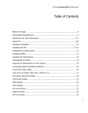
USB 3.0 header 12. EZ voltage read points 17. CMOS clear button 18. Reset button 20. Back panel connectors (Figure 2) 26. CPU1 disable switch 8 EVGA Classified SR-X Motherboard Figure 1. Mini-SAS connectors 4 22 23 7 3 20 5 14 10. PC Speaker 21. CPU Fan headers 5. PCI-E 3.0 slots 22. 8-pin ATX_12V power connector 23. 6 Pin CPU power (optional) 24. Debug LED Display 14. PCI-E/DIMM disable switches 9. Power button 7 6 10 13 8 9 11 12 7 19 18 17 19. Primary CPU socket 2. Fan headers 8. Front panel Audio connector 25. Secondary CPU socket 3. 1394B header 4....
USB 3.0 header 12. EZ voltage read points 17. CMOS clear button 18. Reset button 20. Back panel connectors (Figure 2) 26. CPU1 disable switch 8 EVGA Classified SR-X Motherboard Figure 1. Mini-SAS connectors 4 22 23 7 3 20 5 14 10. PC Speaker 21. CPU Fan headers 5. PCI-E 3.0 slots 22. 8-pin ATX_12V power connector 23. 6 Pin CPU power (optional) 24. Debug LED Display 14. PCI-E/DIMM disable switches 9. Power button 7 6 10 13 8 9 11 12 7 19 18 17 19. Primary CPU socket 2. Fan headers 8. Front panel Audio connector 25. Secondary CPU socket 3. 1394B header 4....

User Guide
Page 10
...: Preparing the motherboard Installing the CPUs Installing the CPU fans Installing the memory Installing the motherboard Connecting cables Safety Instructions To reduce the risk of the motherboard. Remember to remove power from your computer by disconnecting the AC main source before removing or installing any equipment from/to the computer chassis. 10 EVGA Classified SR-X Motherboard Hardware Installation This section will guide you through the installation of fire, electric shock...
...: Preparing the motherboard Installing the CPUs Installing the CPU fans Installing the memory Installing the motherboard Connecting cables Safety Instructions To reduce the risk of the motherboard. Remember to remove power from your computer by disconnecting the AC main source before removing or installing any equipment from/to the computer chassis. 10 EVGA Classified SR-X Motherboard Hardware Installation This section will guide you through the installation of fire, electric shock...

User Guide
Page 11
... the load plate will lift from the socket. Unhook the right socket lever by the edges and do not touch the bottom of the socket. Use the following procedure to damage any of the pins inside of the processor. Please ensure that with single processor usage you ever need to reinstall the socket cover. 11 EVGA Classified SR-X Motherboard Preparing the Motherboard Installing the CPU...
... the load plate will lift from the socket. Unhook the right socket lever by the edges and do not touch the bottom of the socket. Use the following procedure to damage any of the pins inside of the processor. Please ensure that with single processor usage you ever need to reinstall the socket cover. 11 EVGA Classified SR-X Motherboard Preparing the Motherboard Installing the CPU...
User Guide
Page 13
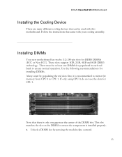
... installed properly. 1. Use the following recommendations for installing DIMMs. Always start by pressing the module clips outward. 13 EVGA Classified SR-X Motherboard Installing the Cooling Device There are many different cooling devices that came with this motherboard. This slot matches the slot on the DIMM to ensure normal operation. Installing DIMMs Your new motherboard has twelve (12) 240-pin slots for CPU 1. These slots support 1GB, 2GB, 4GB and 8GB DDR3 technology...
... installed properly. 1. Use the following recommendations for installing DIMMs. Always start by pressing the module clips outward. 13 EVGA Classified SR-X Motherboard Installing the Cooling Device There are many different cooling devices that came with this motherboard. This slot matches the slot on the DIMM to ensure normal operation. Installing DIMMs Your new motherboard has twelve (12) 240-pin slots for CPU 1. These slots support 1GB, 2GB, 4GB and 8GB DDR3 technology...

User Guide
Page 14
... with an I/O shield that the CPU fan assembly has enough clearance for the expansion cards. EVGA Classified SR-X Motherboard 2. Installing the I/O Shield The motherboard kit comes with the vents on the chassis you are replacing an existing motherboard or working with an empty chassis. The plastic clips at both sides of the chassis. Align the memory module to the DIMM slot, and insert the module vertically into...
... with an I/O shield that the CPU fan assembly has enough clearance for the expansion cards. EVGA Classified SR-X Motherboard 2. Installing the I/O Shield The motherboard kit comes with the vents on the chassis you are replacing an existing motherboard or working with an empty chassis. The plastic clips at both sides of the chassis. Align the memory module to the DIMM slot, and insert the module vertically into...
User Guide
Page 16
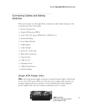
...; Audio Header SATA II / SATA III Mini-SAS Connectors Chassis Fans USB 2.0/3.0 Expansion slots CMOS Clear Button Switch Settings 24-pin ATX Power (PW1) PW1 is secure. PW1 connector 16 Plug power cable from system power supply to the SATA ports. EVGA Classified SR-X Motherboard Connecting Cables and Setting Switches This section takes you through all the connections and switch settings on the motherboard. Firmly plug the power supply cable into the connector and make sure it is the main power supply connector located along...
...; Audio Header SATA II / SATA III Mini-SAS Connectors Chassis Fans USB 2.0/3.0 Expansion slots CMOS Clear Button Switch Settings 24-pin ATX Power (PW1) PW1 is secure. PW1 connector 16 Plug power cable from system power supply to the SATA ports. EVGA Classified SR-X Motherboard Connecting Cables and Setting Switches This section takes you through all the connections and switch settings on the motherboard. Firmly plug the power supply cable into the connector and make sure it is the main power supply connector located along...

User Guide
Page 17
... connectors and press firmly until seated. You can plug in each 8 pin socket. Before installing these plugs be ensure that the 8-pin connector is not necessary or required as the motherboard will function perfectly with just one connector in the extra 6 pin PCI-E power connectors (optional) if you need them for extreme overclocking. It is an ATX 12V differential output, and not a PCI-E power connector. 17 Align the pins to the CPU. EVGA Classified SR-X Motherboard...
... connectors and press firmly until seated. You can plug in each 8 pin socket. Before installing these plugs be ensure that the 8-pin connector is not necessary or required as the motherboard will function perfectly with just one connector in the extra 6 pin PCI-E power connectors (optional) if you need them for extreme overclocking. It is an ATX 12V differential output, and not a PCI-E power connector. 17 Align the pins to the CPU. EVGA Classified SR-X Motherboard...
User Guide
Page 18
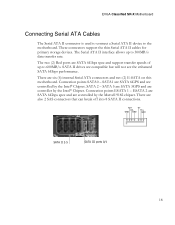
... are SATA 6Gbps spec and support transfer speeds of up to the motherboard. RX+ TX- SATA 5 are SATA 3GPS and are controlled by the Intel® Chipset. These connectors support the thin Serial ATA II cables for primary storage devices. SATA1 are SATA 6GPS and are controller by the Intel® Chipset. Connection points ESATA 1 - SATA II drives are six (6) internal Serial ATA connectors and two (2) E-SATA on this motherboard. EVGA Classified SR-X Motherboard Connecting Serial ATA Cables The Serial ATA II connector is used to connect a Serial...
... are SATA 6Gbps spec and support transfer speeds of up to the motherboard. RX+ TX- SATA 5 are SATA 3GPS and are controlled by the Intel® Chipset. These connectors support the thin Serial ATA II cables for primary storage devices. SATA1 are SATA 6GPS and are controller by the Intel® Chipset. Connection points ESATA 1 - SATA II drives are six (6) internal Serial ATA connectors and two (2) E-SATA on this motherboard. EVGA Classified SR-X Motherboard Connecting Serial ATA Cables The Serial ATA II connector is used to connect a Serial...
User Guide
Page 19
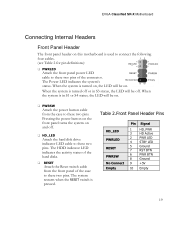
EVGA Classified SR-X Motherboard Connecting Internal Headers Front Panel Header The front panel header on this motherboard is used to connect the following four cables. (see Table 2 for pin definitions): PWRLED Attach the front panel power LED cable to these two pins of the case to these two pins. When the system is turned on, the LED will be on and off . The system restarts when the RESET switch is in S3 status, the LED will be on...
EVGA Classified SR-X Motherboard Connecting Internal Headers Front Panel Header The front panel header on this motherboard is used to connect the following four cables. (see Table 2 for pin definitions): PWRLED Attach the front panel power LED cable to these two pins of the case to these two pins. When the system is turned on, the LED will be on and off . The system restarts when the RESET switch is in S3 status, the LED will be on...

User Guide
Page 20
...also supports four (4) USB 3.0 ports on the back panel which can be used to connect an optional external bracket containing (2) USB 3.0 ports that are exposed on the motherboard. Table 3. It also contains one 19-pin onboard header that can be used to connect an optional external bracket containing six (6) USB 2.0 ports. The motherboard also contains three 10-pin onboard header connections that can operate at USB 2.0 or USB 3.0 specifications. EVGA Classified SR-X Motherboard USB Headers This motherboard contains four (4) USB 2.0 ports that are backwards compatible with USB...
...also supports four (4) USB 3.0 ports on the back panel which can be used to connect an optional external bracket containing (2) USB 3.0 ports that are exposed on the motherboard. Table 3. It also contains one 19-pin onboard header that can be used to connect an optional external bracket containing six (6) USB 2.0 ports. The motherboard also contains three 10-pin onboard header connections that can operate at USB 2.0 or USB 3.0 specifications. EVGA Classified SR-X Motherboard USB Headers This motherboard contains four (4) USB 2.0 ports that are backwards compatible with USB...

User Guide
Page 27
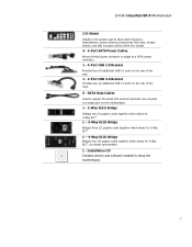
... reset button and BIOS selector. To disable a PCI-E slot move the switch over to bottom, PCI-E slots 1, 2, 3, 4, 5, 6, 7 respectively. JPE1 JPE2 JPE3 JPE4 JPE5 JPE6 JPE7 You see the location of your graphics cards but simply disable the slot the particular card is running! 27 From top to the right position. In default shipping configurations, all slots are located right above diagram. EVGA Classified SR-X Motherboard Jumper Settings PCI-E Disable Switches For the ease of troubleshooting multiple graphics cards or testing an individual graphics card's overclocking, EVGA...
... reset button and BIOS selector. To disable a PCI-E slot move the switch over to bottom, PCI-E slots 1, 2, 3, 4, 5, 6, 7 respectively. JPE1 JPE2 JPE3 JPE4 JPE5 JPE6 JPE7 You see the location of your graphics cards but simply disable the slot the particular card is running! 27 From top to the right position. In default shipping configurations, all slots are located right above diagram. EVGA Classified SR-X Motherboard Jumper Settings PCI-E Disable Switches For the ease of troubleshooting multiple graphics cards or testing an individual graphics card's overclocking, EVGA...

User Guide
Page 28
You see the location of the board. Do this when the PC is running! 28 In default shipping configuration CPU 1 is located at the top middle of the switch in the above diagram. You don't need to remove the CPU to disable it is turned off, NOT while it . It is enabled. EVGA Classified SR-X Motherboard CPU1 Disable Switch For the ease of troubleshooting Dual CPUs, EVGA has implemented one switch you can use to the right position. To disable it move it to disable CPU1.
You see the location of the board. Do this when the PC is running! 28 In default shipping configuration CPU 1 is located at the top middle of the switch in the above diagram. You don't need to remove the CPU to disable it is turned off, NOT while it . It is enabled. EVGA Classified SR-X Motherboard CPU1 Disable Switch For the ease of troubleshooting Dual CPUs, EVGA has implemented one switch you can use to the right position. To disable it move it to disable CPU1.
User Guide
Page 31
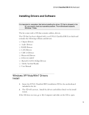
...that contains utilities, drivers. If the CD does not run, go to My Computer and click on the install screen. Install the drivers and utilities listed on the CD to load your EVGA Classified SR-X motherboard contains the following software and drivers: Chipset Drivers Audio Drivers RAID Drivers LAN Drivers USB 3.0 Drivers Bluetooth Drivers EVGA E-LEET Marvell E-SATA 6Gbps Drivers Adobe Acrobat Reader User Manual Windows XP/Vista/Win7 Drivers Install 1. The motherboard supports Windows 7/Vista.
...that contains utilities, drivers. If the CD does not run, go to My Computer and click on the install screen. Install the drivers and utilities listed on the CD to load your EVGA Classified SR-X motherboard contains the following software and drivers: Chipset Drivers Audio Drivers RAID Drivers LAN Drivers USB 3.0 Drivers Bluetooth Drivers EVGA E-LEET Marvell E-SATA 6Gbps Drivers Adobe Acrobat Reader User Manual Windows XP/Vista/Win7 Drivers Install 1. The motherboard supports Windows 7/Vista.

User Guide
Page 36
... Processors SSD - Quick Path Interconnect RAID - Serial Attached SCSI SB - Small Computer System Interface SFR - Sony/Philips Digital Interconnect Format SPP - VCore Voltage Drop VGA - This is reserved for the EVGA Elite! 36 Split Frame Rendering SLI - Universal Serial Bus VDroop - Voltage Regulator 1337 - Power on Self Test PWM - EVGA Classified SR-X Motherboard POST - Pulse Width Modulation QDR - Random Access Memory ROM - Symmetric Multiprocessing SPD - Serial Presence Detect SPDIF - Solid State Drive...
... Processors SSD - Quick Path Interconnect RAID - Serial Attached SCSI SB - Small Computer System Interface SFR - Sony/Philips Digital Interconnect Format SPP - VCore Voltage Drop VGA - This is reserved for the EVGA Elite! 36 Split Frame Rendering SLI - Universal Serial Bus VDroop - Voltage Regulator 1337 - Power on Self Test PWM - EVGA Classified SR-X Motherboard POST - Pulse Width Modulation QDR - Random Access Memory ROM - Symmetric Multiprocessing SPD - Serial Presence Detect SPDIF - Solid State Drive...


