
User Guide
Page 4
... 24 Post Port Debug LED 24 LED Status Indicators 24 Jumper Settings ...25 PCIE Disable Jumper 25 Voltage Measure Point 25 EVGA Control Panel V2 (ECP 26 EVGA Show-Volt ...31 Configuring the BIOS 32 Enter BIOS Setup 33 Main Menu...33 Standard BIOS Features Menu 36 System Time .../ System Date 37 Advanced BIOS Features 37 IDE Configuration 38 Boot Settings Configuration 38 AHCI Configuration 38 USB Configuration 39 Advanced Chipset Features 39 North...
... 24 Post Port Debug LED 24 LED Status Indicators 24 Jumper Settings ...25 PCIE Disable Jumper 25 Voltage Measure Point 25 EVGA Control Panel V2 (ECP 26 EVGA Show-Volt ...31 Configuring the BIOS 32 Enter BIOS Setup 33 Main Menu...33 Standard BIOS Features Menu 36 System Time .../ System Date 37 Advanced BIOS Features 37 IDE Configuration 38 Boot Settings Configuration 38 AHCI Configuration 38 USB Configuration 39 Advanced Chipset Features 39 North...

User Guide
Page 6
Power Management Features 45 Figure 9. Standard BIOS Features Menu 36 Figure 4. Boot Configuration Features 44 Figure 8. Frequency/Voltage Control 47 6 Hardware Health Configure 46 Figure 10. CMOS Setup Utility Main Menu 34 Figure 3. Advanced Chipset Features 39 Figure 6. Advanced BIOS Features 38 Figure 5. PCI/PNP Resource Management 42 Figure 7. List of Figures Figure 1. PW1 Motherboard Connector 16 Figure 2.
Power Management Features 45 Figure 9. Standard BIOS Features Menu 36 Figure 4. Boot Configuration Features 44 Figure 8. Frequency/Voltage Control 47 6 Hardware Health Configure 46 Figure 10. CMOS Setup Utility Main Menu 34 Figure 3. Advanced Chipset Features 39 Figure 6. Advanced BIOS Features 38 Figure 5. PCI/PNP Resource Management 42 Figure 7. List of Figures Figure 1. PW1 Motherboard Connector 16 Figure 2.

User Guide
Page 8
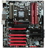
...'s Operating systems: Supports Windows XP 32bit/64bit, Windows Vista 32bit/64bit, and Windows 7 32bit/64bit Intel P55 Express Chipset System Memory support Supports dual channel DDR3-2600+. EVGA P55 Classified 200 Motherboard Motherboard Specifications Size ATX form factor of DDR3 memory. USB 2.0 Ports Supports hot plug Thirteen...
...'s Operating systems: Supports Windows XP 32bit/64bit, Windows Vista 32bit/64bit, and Windows 7 32bit/64bit Intel P55 Express Chipset System Memory support Supports dual channel DDR3-2600+. EVGA P55 Classified 200 Motherboard Motherboard Specifications Size ATX form factor of DDR3 memory. USB 2.0 Ports Supports hot plug Thirteen...

User Guide
Page 26
CPU Vcore voltage CPU VTT voltage Memory voltage P55 chipset voltage CPU PLL voltage Ground EVGA Control Panel V2 (ECP) For the convenience of users, EVGA has bundled an easy to Access Control Panel: To use the ECP, simply hook up the black ECP Cable to the motherboard at the ECP header location. (See visual guide) The other end of the Cable should be connected to the ECP as shown: 26
CPU Vcore voltage CPU VTT voltage Memory voltage P55 chipset voltage CPU PLL voltage Ground EVGA Control Panel V2 (ECP) For the convenience of users, EVGA has bundled an easy to Access Control Panel: To use the ECP, simply hook up the black ECP Cable to the motherboard at the ECP header location. (See visual guide) The other end of the Cable should be connected to the ECP as shown: 26

User Guide
Page 32
Configuring the BIOS This section discusses how to change the system settings through the BIOS Setup menus. This section includes the following information: Enter BIOS Setup Main Menu Standard BIOS Features Advanced BIOS Features Advanced Chipset Features PCI/PnP Resource Management Boot Configuration Features Power Management Features Hardware Health Configure Frequency/Voltage Control 32 Descriptions of the BIOS parameters are also provided.
Configuring the BIOS This section discusses how to change the system settings through the BIOS Setup menus. This section includes the following information: Enter BIOS Setup Main Menu Standard BIOS Features Advanced BIOS Features Advanced Chipset Features PCI/PnP Resource Management Boot Configuration Features Power Management Features Hardware Health Configure Frequency/Voltage Control 32 Descriptions of the BIOS parameters are also provided.
User Guide
Page 34
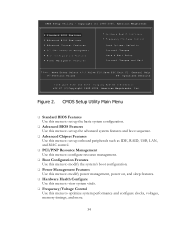
...configuration. Advanced BIOS Features Use this menu to set up the advanced system features and boot sequence. Advanced Chipset Features Use this menu to set up onboard peripherals such as IDE, RAID, USB, LAN, and MAC control. ...memory timings, and more. 34 Copyright (C) 1985-2005, American Megatrends Standard BIOS Features Advanced BIOS Features Advanced Chipset Features PCI/PNP Resource Management Boot Configuration Features Power Management Features Hardware Health Configure Frequency/Voltage...
...configuration. Advanced BIOS Features Use this menu to set up the advanced system features and boot sequence. Advanced Chipset Features Use this menu to set up onboard peripherals such as IDE, RAID, USB, LAN, and MAC control. ...memory timings, and more. 34 Copyright (C) 1985-2005, American Megatrends Standard BIOS Features Advanced BIOS Features Advanced Chipset Features PCI/PNP Resource Management Boot Configuration Features Power Management Features Hardware Health Configure Frequency/Voltage...

User Guide
Page 39
... [Press Enter] Move Enter:Select +/-/:Value F10:Save ESC:Exit F1:General Help F7:Previous Values F9:Optimized Defaults Figure 5. Advanced Chipset Features North Bridge Configuration This option menu will allow you to enable Legacy USB support, force USB 1.1 mode and more . 39 ...CMOS Setup Utility - Copyright (C) 1985-2005, American Megatrends Advanced Chipset Features Advanced Chipset Settings WARNING: Setting wrong values in below sections may cause system to change the settings. Configuring the BIOS USB Configuration This ...
... [Press Enter] Move Enter:Select +/-/:Value F10:Save ESC:Exit F1:General Help F7:Previous Values F9:Optimized Defaults Figure 5. Advanced Chipset Features North Bridge Configuration This option menu will allow you to enable Legacy USB support, force USB 1.1 mode and more . 39 ...CMOS Setup Utility - Copyright (C) 1985-2005, American Megatrends Advanced Chipset Features Advanced Chipset Settings WARNING: Setting wrong values in below sections may cause system to change the settings. Configuring the BIOS USB Configuration This ...

User Guide
Page 40
It is enabled the onboard Post Port LED will display the CPU temperature. 40 The Advanced Chipset Features menu also allows you to enable/disable some onboard devices, they are using an external Network Controller, such as follows: HD Audio ... primary network controller. This setting can help improve performance in a virtualized environment, it is recommended to leave this enabled, unless you are as an EVGA Killer Xeno card. LAN2 Controller This function allows you to enable or disable the onboard secondary network controller. It is recommended to adjust these...
It is enabled the onboard Post Port LED will display the CPU temperature. 40 The Advanced Chipset Features menu also allows you to enable/disable some onboard devices, they are using an external Network Controller, such as follows: HD Audio ... primary network controller. This setting can help improve performance in a virtualized environment, it is recommended to leave this enabled, unless you are as an EVGA Killer Xeno card. LAN2 Controller This function allows you to enable or disable the onboard secondary network controller. It is recommended to adjust these...

User Guide
Page 49
... the BIOS Installing Drivers and Software The CD that has been shipped with the EVGA P55 Classified 200 Motherboard contains the following software and drivers: Chipset Drivers Audio drivers LAN Drivers RAID Drivers EVGA E-LEET Overclocking Utility Adobe Acrobat Reader User's Manual Windows XP/Vista/7 Driver...
... the BIOS Installing Drivers and Software The CD that has been shipped with the EVGA P55 Classified 200 Motherboard contains the following software and drivers: Chipset Drivers Audio drivers LAN Drivers RAID Drivers EVGA E-LEET Overclocking Utility Adobe Acrobat Reader User's Manual Windows XP/Vista/7 Driver...

User Guide
Page 51
...7C 84 85 87 8C 8D 8E 90 A1 Description Detect Mouse Detect Keyboard Test input devices Early POST initialization of chipset registers Relocate System Management interrupt vector Uncompress and initialize BIOS module Initialize devices primary Initialize devices secondary Initialize output devices ...module Display sign-on message Initialize USB controller Initialize DMAC-1 & DMAC-2 Initialize real time clock Test system memory Initialization of chipset registers Detect coprocessor Update CMOS memory size Initialize NUM-LOCK Initialize Int-13 Initialize IPL devices Generate and write contents of ...
...7C 84 85 87 8C 8D 8E 90 A1 Description Detect Mouse Detect Keyboard Test input devices Early POST initialization of chipset registers Relocate System Management interrupt vector Uncompress and initialize BIOS module Initialize devices primary Initialize devices secondary Initialize output devices ...module Display sign-on message Initialize USB controller Initialize DMAC-1 & DMAC-2 Initialize real time clock Test system memory Initialization of chipset registers Detect coprocessor Update CMOS memory size Initialize NUM-LOCK Initialize Int-13 Initialize IPL devices Generate and write contents of ...