
User Guide
Page 3
... You Begin...7 Parts NOT in the Kit 7 EVGA P55 Classified 200 Motherboard 8 Motherboard Specifications 8 Hardware Installation 10 Safety Instructions 10 Preparing the Motherboard 11 Installing the CPU 11 Installing the CPU Fan 12 Installing System Memory (DIMMs 13 Installing the Motherboard 13 Installing the I/O Shield 14 Securing the Motherboard into a System Case 15 Connecting Cables 15 24-pin ATX Power (PW1 16 8-pin ATX 12V Power (PW12 16 Connecting Serial ATA Cables 17 Connecting Internal Headers 18 Front Panel Header 18 IEEE1394a (Firewire 19 USB Headers 20 Audio ...21...
... You Begin...7 Parts NOT in the Kit 7 EVGA P55 Classified 200 Motherboard 8 Motherboard Specifications 8 Hardware Installation 10 Safety Instructions 10 Preparing the Motherboard 11 Installing the CPU 11 Installing the CPU Fan 12 Installing System Memory (DIMMs 13 Installing the Motherboard 13 Installing the I/O Shield 14 Securing the Motherboard into a System Case 15 Connecting Cables 15 24-pin ATX Power (PW1 16 8-pin ATX 12V Power (PW12 16 Connecting Serial ATA Cables 17 Connecting Internal Headers 18 Front Panel Header 18 IEEE1394a (Firewire 19 USB Headers 20 Audio ...21...

User Guide
Page 4
Expansion Slots 22 PCI Express x16/x8/x4 Slots 22 Onboard Buttons ...23 Clear CMOS Button 23 RESET and POWER Button 23 Post Port Debug LED and LED Status Indicators 24 Post Port Debug LED 24 LED Status Indicators 24 Jumper Settings ...25 PCIE Disable Jumper 25 Voltage Measure Point 25 EVGA Control Panel V2 (ECP 26 EVGA Show-Volt ...31 Configuring the BIOS 32 Enter BIOS Setup 33 Main Menu...33 Standard BIOS Features Menu 36 System Time / System Date 37 Advanced BIOS Features 37 IDE Configuration 38 Boot Settings Configuration 38 AHCI Configuration 38 USB Configuration 39 ...
Expansion Slots 22 PCI Express x16/x8/x4 Slots 22 Onboard Buttons ...23 Clear CMOS Button 23 RESET and POWER Button 23 Post Port Debug LED and LED Status Indicators 24 Post Port Debug LED 24 LED Status Indicators 24 Jumper Settings ...25 PCIE Disable Jumper 25 Voltage Measure Point 25 EVGA Control Panel V2 (ECP 26 EVGA Show-Volt ...31 Configuring the BIOS 32 Enter BIOS Setup 33 Main Menu...33 Standard BIOS Features Menu 36 System Time / System Date 37 Advanced BIOS Features 37 IDE Configuration 38 Boot Settings Configuration 38 AHCI Configuration 38 USB Configuration 39 ...

User Guide
Page 5
...47 CPU Fan Mode Setting 47 Frequency/Voltage Control Menu 47 Memory Configure 48 CPU Configuration 48 Installing Drivers and Software 49 Windows XP/Vista/7 Driver Installation 49 Appendix A. EVGA P55 Classified 200 Motherboard Clear NVRAM...42 Plug & Play O/S 42 PCI Latency Timer 42 Allocate IRQ to PCI VGA 43 Palette Snooping 43 PCI IDE BusMaster 43 OffBoard PCI/ISA IDE Card 43 IRQ Settings ...43 DMA Channel ...43 Reserved Memory Size 43 Boot Configuration Features 44 Boot Device Priority 44 Hard Disk Drives 44 CD/DVD Drives 45 Power Management Features 45 ACPI Configuration...
...47 CPU Fan Mode Setting 47 Frequency/Voltage Control Menu 47 Memory Configure 48 CPU Configuration 48 Installing Drivers and Software 49 Windows XP/Vista/7 Driver Installation 49 Appendix A. EVGA P55 Classified 200 Motherboard Clear NVRAM...42 Plug & Play O/S 42 PCI Latency Timer 42 Allocate IRQ to PCI VGA 43 Palette Snooping 43 PCI IDE BusMaster 43 OffBoard PCI/ISA IDE Card 43 IRQ Settings ...43 DMA Channel ...43 Reserved Memory Size 43 Boot Configuration Features 44 Boot Device Priority 44 Hard Disk Drives 44 CD/DVD Drives 45 Power Management Features 45 ACPI Configuration...

User Guide
Page 7
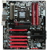
... Memory Socket 1156 or Socket 775 Cooling fan PCI Express or PCI Graphics Card Power Supply EVGA assumes you will need to reinstall an operating system even though the current hard disk may already have purchased all the hardware necessary to allow for proper system functionality. When replacing a motherboard in the Kit This kit contains all the necessary parts needed to install and connect your new EVGA...
... Memory Socket 1156 or Socket 775 Cooling fan PCI Express or PCI Graphics Card Power Supply EVGA assumes you will need to reinstall an operating system even though the current hard disk may already have purchased all the hardware necessary to allow for proper system functionality. When replacing a motherboard in the Kit This kit contains all the necessary parts needed to install and connect your new EVGA...

User Guide
Page 15
... include: Power Connections 24-pin ATX power (PW1) 8-pin ATX 12V power (PW12) Internal Headers Front panel IEEE 1394a USB Headers Audio Serial ATA II USB 2.0 Expansion slots CMOS Clear Button 15 In most cases, it is recommended that you through all the necessary connections on the motherboard, it is aligned with the chassis vents according to the fan assembly instruction. 5. Ensure that stud to secure the motherboard using a minimum of nine...
... include: Power Connections 24-pin ATX power (PW1) 8-pin ATX 12V power (PW12) Internal Headers Front panel IEEE 1394a USB Headers Audio Serial ATA II USB 2.0 Expansion slots CMOS Clear Button 15 In most cases, it is recommended that you through all the necessary connections on the motherboard, it is aligned with the chassis vents according to the fan assembly instruction. 5. Ensure that stud to secure the motherboard using a minimum of nine...

User Guide
Page 18
... the system is turned off, the LED is off rather than using the onboard button. HD_LED Attach the hard disk drive indicator LED cable to these two pins of the hard disks. RESET Attach the Reset switch cable from the case to these two pins. Connecting Internal Headers Front Panel Header The front panel header on this motherboard is one connector used to connect the following four cables. (see Table 2 for pin definitions): PWRLED Attach the front panel power LED cable to these...
... the system is turned off, the LED is off rather than using the onboard button. HD_LED Attach the hard disk drive indicator LED cable to these two pins of the hard disks. RESET Attach the Reset switch cable from the case to these two pins. Connecting Internal Headers Front Panel Header The front panel header on this motherboard is one connector used to connect the following four cables. (see Table 2 for pin definitions): PWRLED Attach the front panel power LED cable to these...

User Guide
Page 22
Secure the card's metal bracket to the chassis back panel with the screw used to hold the blank cover. 22 If the card is not seated properly, it could cause a short across the pins. Expansion Slots PCI Express x16/x8/x4 Slots These PCI Express slots are reserved for Graphic Cards and PCI Express x1 and x4 devices. When installing a PCI Express Graphic Card, be sure the retention clip snaps and locks the card into place. The design of this motherboard supports multiple Graphic Card technology.
Secure the card's metal bracket to the chassis back panel with the screw used to hold the blank cover. 22 If the card is not seated properly, it could cause a short across the pins. Expansion Slots PCI Express x16/x8/x4 Slots These PCI Express slots are reserved for Graphic Cards and PCI Express x1 and x4 devices. When installing a PCI Express Graphic Card, be sure the retention clip snaps and locks the card into place. The design of this motherboard supports multiple Graphic Card technology.

User Guide
Page 25
.... Voltage Measure Point The motherboard is running! You can use to know. 25 Jumper Settings PCIE Disable Jumper For the ease of troubleshooting Multiple Video Cards, or testing individual Video Card's Overclocking, EVGA has implemented 3 Jumpers you can use a voltmeter to measure the voltage you want to disable individual PCIE slots. The PCIe disable jumpers are located right beside the 24pin ATX Connector. To disable a PCIE Slot, move the jumper over to the right position. Do this when the PC is turned...
.... Voltage Measure Point The motherboard is running! You can use to know. 25 Jumper Settings PCIE Disable Jumper For the ease of troubleshooting Multiple Video Cards, or testing individual Video Card's Overclocking, EVGA has implemented 3 Jumpers you can use a voltmeter to measure the voltage you want to disable individual PCIE slots. The PCIe disable jumpers are located right beside the 24pin ATX Connector. To disable a PCIE Slot, move the jumper over to the right position. Do this when the PC is turned...
User Guide
Page 33
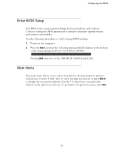
... following procedure to the AMI BIOS CMOS Setup Utility. Press F2 to Load Defaults, DEL to the previous menu, press Esc. 33 Correctly setting the BIOS parameters is the communication bridge between hardware and software. Use the arrow keys to position the selector in the option you to verify/change BIOS settings. 3. Use the following message briefly displays at the bottom of setup functions and two exit...
... following procedure to the AMI BIOS CMOS Setup Utility. Press F2 to Load Defaults, DEL to the previous menu, press Esc. 33 Correctly setting the BIOS parameters is the communication bridge between hardware and software. Use the arrow keys to position the selector in the option you to verify/change BIOS settings. 3. Use the following message briefly displays at the bottom of setup functions and two exit...
User Guide
Page 34
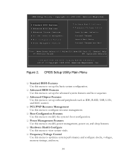
... Enter:Select +/-/:Valve F10:Save ESC:Exit F1: General Help F7:Previous Values F9: Optimized Defaults Configure Time and Date. CMOS Setup Utility Main Menu Standard BIOS Features Use this menu to set up the basic system configuration. Advanced BIOS Features Use this menu to set up the advanced system features and boot sequence. Advanced Chipset Features Use this menu to set up onboard peripherals such as IDE, RAID, USB, LAN, and MAC control. PCI...
... Enter:Select +/-/:Valve F10:Save ESC:Exit F1: General Help F7:Previous Values F9: Optimized Defaults Configure Time and Date. CMOS Setup Utility Main Menu Standard BIOS Features Use this menu to set up the basic system configuration. Advanced BIOS Features Use this menu to set up the advanced system features and boot sequence. Advanced Chipset Features Use this menu to set up onboard peripherals such as IDE, RAID, USB, LAN, and MAC control. PCI...

User Guide
Page 38
... Values F9:Optimized Defaults Figure 4. Advanced BIOS Features IDE Configuration Use this option to configure various system options, such as S.M.A.R.T. Boot Settings Configuration Use this to configure your storage drivers and to change advanced AHCI settings, such as Bootup Num-Lock status, Quiet Boot and other advanced features. AHCI Configuration This menu will allow you to enable RAID or switch between IDE and AHCI mode. status and more. 38 Please note for Windows Vista / Windows 7, it is recommended to malfunction. CMOS Setup Utility -
... Values F9:Optimized Defaults Figure 4. Advanced BIOS Features IDE Configuration Use this option to configure various system options, such as S.M.A.R.T. Boot Settings Configuration Use this to configure your storage drivers and to change advanced AHCI settings, such as Bootup Num-Lock status, Quiet Boot and other advanced features. AHCI Configuration This menu will allow you to enable RAID or switch between IDE and AHCI mode. status and more. 38 Please note for Windows Vista / Windows 7, it is recommended to malfunction. CMOS Setup Utility -

User Guide
Page 39
... [Disabled] HD Audio Controller [Enabled] IEEE1394 [Enabled] LAN1 Controller [Enabled] LAN2 Controller [Enabled] LAN Boot [Disabled] ESATA Controller [Enabled] ESATA Boot [Disabled] PE1 Slot [Auto] P80 Show CPU Temperature Slot[Enabled] ME Subsystem Configuration [Press Enter] Move Enter:Select +/-/:Value F10:Save ESC:Exit F1:General Help F7:Previous Values F9:Optimized Defaults Figure 5. Advanced Chipset Features North Bridge Configuration This option menu will allow you to enable Legacy USB support, force USB 1.1 mode and more . 39 CMOS Setup Utility...
... [Disabled] HD Audio Controller [Enabled] IEEE1394 [Enabled] LAN1 Controller [Enabled] LAN2 Controller [Enabled] LAN Boot [Disabled] ESATA Controller [Enabled] ESATA Boot [Disabled] PE1 Slot [Auto] P80 Show CPU Temperature Slot[Enabled] ME Subsystem Configuration [Press Enter] Move Enter:Select +/-/:Value F10:Save ESC:Exit F1:General Help F7:Previous Values F9:Optimized Defaults Figure 5. Advanced Chipset Features North Bridge Configuration This option menu will allow you to enable Legacy USB support, force USB 1.1 mode and more . 39 CMOS Setup Utility...

User Guide
Page 40
... system setups. It is enabled the onboard Post Port LED will allow you to set the onboard audio function. It is recommended to leave this enabled, unless you are using an external Network Controller, such as an EVGA Killer Xeno card. ESATA Controller This function allows you to enable or disable the SATA interface. PE1 Slot This function allows you to enable or disable the PE1 Slot. P80 Show CPU Temperature When...
... system setups. It is enabled the onboard Post Port LED will allow you to set the onboard audio function. It is recommended to leave this enabled, unless you are using an external Network Controller, such as an EVGA Killer Xeno card. ESATA Controller This function allows you to enable or disable the SATA interface. PE1 Slot This function allows you to enable or disable the PE1 Slot. P80 Show CPU Temperature When...

User Guide
Page 42
... PCI IDE BusMaster OffBoard PCI/ISA IDE Card IRQ3 IRQ4 IRQ5 IRQ7 IRQ9 IRQ10 [No] [No] [64] [Yes] [Disabled] [Enabled] [Auto] [Available] [Available] [Available] [Available] [Available] [Available] Move Enter:Select +/-/:Value F10:Save ESC:Exit F1:General Help F7:Previous Values F9:Optimized Defaults Figure 6. A setting of PCI clocks. 42 Plug & Play O/S This function sets whether the O/S or BIOS configures Plug and Play devices. Help Item Clear NVRAM during System Boot. CMOS Setup Utility...
... PCI IDE BusMaster OffBoard PCI/ISA IDE Card IRQ3 IRQ4 IRQ5 IRQ7 IRQ9 IRQ10 [No] [No] [64] [Yes] [Disabled] [Enabled] [Auto] [Available] [Available] [Available] [Available] [Available] [Available] Move Enter:Select +/-/:Value F10:Save ESC:Exit F1:General Help F7:Previous Values F9:Optimized Defaults Figure 6. A setting of PCI clocks. 42 Plug & Play O/S This function sets whether the O/S or BIOS configures Plug and Play devices. Help Item Clear NVRAM during System Boot. CMOS Setup Utility...

User Guide
Page 44
...:Optimized Defaults Move Enter:Select +/-/PU/PD:Value F10:Save ESC:Exit F1:General Help F5:Previous Values F6:Fail-Safe Defaults F7:Optimized Defaults Figure 7. Boot Configuration Features Select Boot Configuration Features from the CMOS Setup Utility menu and press Enter to display the settings. Copyright (C) 1985-2005, American Megatrends Boot Configuration Features Boot Device Priority Hard Disk Drives CD/DVD Drives [Press Enter] [Press Enter] [Press Enter] Help Item Specifies the Boot Device Priority sequence. CMOS Setup Utility -
...:Optimized Defaults Move Enter:Select +/-/PU/PD:Value F10:Save ESC:Exit F1:General Help F5:Previous Values F6:Fail-Safe Defaults F7:Optimized Defaults Figure 7. Boot Configuration Features Select Boot Configuration Features from the CMOS Setup Utility menu and press Enter to display the settings. Copyright (C) 1985-2005, American Megatrends Boot Configuration Features Boot Device Priority Hard Disk Drives CD/DVD Drives [Press Enter] [Press Enter] [Press Enter] Help Item Specifies the Boot Device Priority sequence. CMOS Setup Utility -

User Guide
Page 45
... CD/DVD boot priority sequence. Move Enter:Select +/-/:Value F10:Save ESC:Exit F1:General Help F7:Previous Values F9:Optimized Defaults Move Enter:Select +/-/PU/PD:Value F10:Save ESC:Exit F1:General Help F5:Previous Values F6:Fail-Safe Defaults F7:Optimized Defaults Figure 8. Configuring the BIOS CD/DVD Drives This option menu allows you specification of Advanced ACPI configurations. 45 Assertion Width [4 to display the settings. CMOS Setup Utility - Power...
... CD/DVD boot priority sequence. Move Enter:Select +/-/:Value F10:Save ESC:Exit F1:General Help F7:Previous Values F9:Optimized Defaults Move Enter:Select +/-/PU/PD:Value F10:Save ESC:Exit F1:General Help F5:Previous Values F6:Fail-Safe Defaults F7:Optimized Defaults Figure 8. Configuring the BIOS CD/DVD Drives This option menu allows you specification of Advanced ACPI configurations. 45 Assertion Width [4 to display the settings. CMOS Setup Utility - Power...

User Guide
Page 46
... Temperature Sensor System Temperature Sensor :34C/93F :48C/118F :34C/93F Help Item Enables Hardware Health Monitoring Device. Assertion Width This function allows adjustment of the AC Power Loss parameters. Restore on AC Power Loss This menu allows adjustment of the SLP assertion width. Hardware Health Configure Select Hardware Health Configure from the CMOS Setup Utility menu and press Enter to display the settings. Hardware Health Configure 46 CPU Fan Speed Power Fan Speed Chassis Fan Speed...
... Temperature Sensor System Temperature Sensor :34C/93F :48C/118F :34C/93F Help Item Enables Hardware Health Monitoring Device. Assertion Width This function allows adjustment of the AC Power Loss parameters. Restore on AC Power Loss This menu allows adjustment of the SLP assertion width. Hardware Health Configure Select Hardware Health Configure from the CMOS Setup Utility menu and press Enter to display the settings. Hardware Health Configure 46 CPU Fan Speed Power Fan Speed Chassis Fan Speed...
User Guide
Page 47
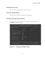
...Strap [Auto] Main Level Extreme Cooling [Disabled] EVGA VDroop Control [With VDroop] Current CPU VCore : 1.20000V Bootup CPU VCore [Auto] Eventual CPU VCore [Auto] Current Dimm Voltage : 1.50V Move Enter:Select +/-/:Value F10:Save ESC:Exit F1:General Help F7:Previous Values F9:Optimized Defaults Figure 10. Frequency/Voltage Control Menu Select Frequency/Voltage Control from the CMOS Setup Utility menu and press Enter to display the settings. CPU Fan Mode Setting This function allows change of the fan mode configuration. CMOS Setup Utility - Configuring the BIOS...
...Strap [Auto] Main Level Extreme Cooling [Disabled] EVGA VDroop Control [With VDroop] Current CPU VCore : 1.20000V Bootup CPU VCore [Auto] Eventual CPU VCore [Auto] Current Dimm Voltage : 1.50V Move Enter:Select +/-/:Value F10:Save ESC:Exit F1:General Help F7:Previous Values F9:Optimized Defaults Figure 10. Frequency/Voltage Control Menu Select Frequency/Voltage Control from the CMOS Setup Utility menu and press Enter to display the settings. CPU Fan Mode Setting This function allows change of the fan mode configuration. CMOS Setup Utility - Configuring the BIOS...

User Guide
Page 49
... Insert the Intel P55 installation CD for the motherboard included in the kit. 2. Configuring the BIOS Installing Drivers and Software The CD that has been shipped with the EVGA P55 Classified 200 Motherboard contains the following software and drivers: Chipset Drivers Audio drivers LAN Drivers RAID Drivers EVGA E-LEET Overclocking Utility Adobe Acrobat Reader User's Manual Windows XP/Vista/7 Driver Installation 1. The CD will autorun, install the drivers and utilities listed on the CD...
... Insert the Intel P55 installation CD for the motherboard included in the kit. 2. Configuring the BIOS Installing Drivers and Software The CD that has been shipped with the EVGA P55 Classified 200 Motherboard contains the following software and drivers: Chipset Drivers Audio drivers LAN Drivers RAID Drivers EVGA E-LEET Overclocking Utility Adobe Acrobat Reader User's Manual Windows XP/Vista/7 Driver Installation 1. The CD will autorun, install the drivers and utilities listed on the CD...

User Guide
Page 50
... onboard the motherboard. Appendix A. This Debug LED will also display current CPU temperatures after the system has fully booted into the Operating System. Check Battery Power and CMOS Initialize interrupt controlling hardware/vector table Initialize system timer Fixes CPU POST interface calling pointer Primary initialization of CPU Secondary initialization of CPU Set up boot strap processor information Set up boot strap processor for POST Enumerate and set up application processors Re-enable cache for the EVGA...
... onboard the motherboard. Appendix A. This Debug LED will also display current CPU temperatures after the system has fully booted into the Operating System. Check Battery Power and CMOS Initialize interrupt controlling hardware/vector table Initialize system timer Fixes CPU POST interface calling pointer Primary initialization of CPU Secondary initialization of CPU Set up boot strap processor information Set up boot strap processor for POST Enumerate and set up application processors Re-enable cache for the EVGA...


