
User Manual
Page 4
... ix Intentions of the Kit x EVGA nForce 790i Motherboard 1 Motherboard Specifications 1 Unpacking and Parts Descriptions 4 Unpacking ...4 Equipment ...4 EVGA nForce 790i Ultra SLI Motherboard 5 Hardware Installation 8 Safety Instructions 8 Preparing the Motherboard 9 Installing the CPU 9 Installing the CPU Fan 10 Installing Memory DIMMs 10 Installing the Motherboard 12 Installing the I/O Shield 12 Securing the Motherboard into the Chassis 13 Connecting...
... ix Intentions of the Kit x EVGA nForce 790i Motherboard 1 Motherboard Specifications 1 Unpacking and Parts Descriptions 4 Unpacking ...4 Equipment ...4 EVGA nForce 790i Ultra SLI Motherboard 5 Hardware Installation 8 Safety Instructions 8 Preparing the Motherboard 9 Installing the CPU 9 Installing the CPU Fan 10 Installing Memory DIMMs 10 Installing the Motherboard 12 Installing the I/O Shield 12 Securing the Motherboard into the Chassis 13 Connecting...
User Manual
Page 5
nForce 790i Ultra SLI Motherboard Connecting IDE Hard Disk Drives 16 Connecting Serial ATA Cables 18 Connecting Internal Headers 19 Front Panel Header 19 IEEE 1394a...20 USB Headers 21 ... Channel and SATA Channel 34 Drive A...37 Halt On ...37 Memory ...38 Advanced BIOS Features 39 Removable Device Priority 40 Hard Disk Boot Priority 40 EVGA Corporation iv January 11, 2008 | DU-03751-001_v01
nForce 790i Ultra SLI Motherboard Connecting IDE Hard Disk Drives 16 Connecting Serial ATA Cables 18 Connecting Internal Headers 19 Front Panel Header 19 IEEE 1394a...20 USB Headers 21 ... Channel and SATA Channel 34 Drive A...37 Halt On ...37 Memory ...38 Advanced BIOS Features 39 Removable Device Priority 40 Hard Disk Boot Priority 40 EVGA Corporation iv January 11, 2008 | DU-03751-001_v01

User Manual
Page 6
nForce 790i SLI Motherboard Network Boot Priority 40 CPU Internal Cache 41 Quick Power On Self Test 41 First/Second/Third Boot Device 41 Boot Other Device 42 Boot ... 58 System BIOS Cacheable 58 Integrated Peripherals Menu 59 IDE Function Setup 60 RAID Config ...61 USB Config ...61 MAC Config...62 IEEE1394 controller 62 EVGA Corporation January 11, 2008 | DU-03751-001_v01 v
nForce 790i SLI Motherboard Network Boot Priority 40 CPU Internal Cache 41 Quick Power On Self Test 41 First/Second/Third Boot Device 41 Boot Other Device 42 Boot ... 58 System BIOS Cacheable 58 Integrated Peripherals Menu 59 IDE Function Setup 60 RAID Config ...61 USB Config ...61 MAC Config...62 IEEE1394 controller 62 EVGA Corporation January 11, 2008 | DU-03751-001_v01 v
User Manual
Page 7
nForce 790i Ultra SLI Motherboard HD Audio...62 IDE HDD Block Mode 62 Onboard FDC Controller 63 Onboard Serial Port 1 63 Power Management Setup Menu 63 ACPI Function ...64 ACPI ... Software 75 NVIDIA Performance Group of NVIDIA Control Panel 76 Device Settings 77 Current Hardware Settings 78 Dynamic BIOS Access 85 View System Information 86 EVGA Corporation vi January 11, 2008 | DU-03751-001_v01
nForce 790i Ultra SLI Motherboard HD Audio...62 IDE HDD Block Mode 62 Onboard FDC Controller 63 Onboard Serial Port 1 63 Power Management Setup Menu 63 ACPI Function ...64 ACPI ... Software 75 NVIDIA Performance Group of NVIDIA Control Panel 76 Device Settings 77 Current Hardware Settings 78 Dynamic BIOS Access 85 View System Information 86 EVGA Corporation vi January 11, 2008 | DU-03751-001_v01

User Manual
Page 8
nForce 790i SLI Motherboard Profile Policies...87 Manage Your System BIOS 88 NVIDIA System Monitor 89 Appendix A. EVGA Corporation January 11, 2008 | DU-03751-001_v01 vii POST Codes for Tritium Platform 95 Appendix B. Bookmark not defined. Configuring an SLI Configuration 105 SLI Connector ...106 ForceWare Driver 106 Enabling 3-Way SLI 108 Verifying 3-way SLI is Active 110 Index Error!
nForce 790i SLI Motherboard Profile Policies...87 Manage Your System BIOS 88 NVIDIA System Monitor 89 Appendix A. EVGA Corporation January 11, 2008 | DU-03751-001_v01 vii POST Codes for Tritium Platform 95 Appendix B. Bookmark not defined. Configuring an SLI Configuration 105 SLI Connector ...106 ForceWare Driver 106 Enabling 3-Way SLI 108 Verifying 3-way SLI is Active 110 Index Error!
User Manual
Page 10
...microprocessor: Intel Core 2 Extreme, Intel Core 2 Quad, Intel Core 2 Duo Pentium EE, Pentium D, Pentium ‰ Cooling fan for your new EVGA a nForce® 790i Ultra SLI motherboard. As a rule, for one GPU you need a minimum of a 1000 W power supply. However, it does not contain the following items that... channel DDR3 800/1066/1333, and up to www.slizone.com. If you install. EVGA Corporation January 11, 2008 | DU-03751-001_v01 ix Supports up to require more power. nForce 790i SLI Motherboard Before You Begin... To calculate the power you go to 8 GBs DDR3 memory. &#...
...microprocessor: Intel Core 2 Extreme, Intel Core 2 Quad, Intel Core 2 Duo Pentium EE, Pentium D, Pentium ‰ Cooling fan for your new EVGA a nForce® 790i Ultra SLI motherboard. As a rule, for one GPU you need a minimum of a 1000 W power supply. However, it does not contain the following items that... channel DDR3 800/1066/1333, and up to www.slizone.com. If you install. EVGA Corporation January 11, 2008 | DU-03751-001_v01 ix Supports up to require more power. nForce 790i SLI Motherboard Before You Begin... To calculate the power you go to 8 GBs DDR3 memory. &#...

User Manual
Page 11
If you are replacing a motherboard, you will need many of the cables. EVGA Corporation x January 11, 2008 | DU-03751-001_v01 If however, you are building a PC, you will use most of the cables provided in a PC cabinet, you will not need to install the motherboard into a PC cabinet. nForce 790i Ultra SLI Motherboard Intentions of the Kit This kit provides you with the motherboard and all connecting cables necessary to reinstall an operating system even though the current drives have an operating system. When replacing a motherboard in the kit.
If you are replacing a motherboard, you will need many of the cables. EVGA Corporation x January 11, 2008 | DU-03751-001_v01 If however, you are building a PC, you will use most of the cables provided in a PC cabinet, you will not need to install the motherboard into a PC cabinet. nForce 790i Ultra SLI Motherboard Intentions of the Kit This kit provides you with the motherboard and all connecting cables necessary to reinstall an operating system even though the current drives have an operating system. When replacing a motherboard in the kit.
User Manual
Page 12
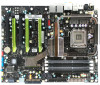
... you get innovative NVIDIA SLI Technology for buying the EVGA NFORCE 790i Ultra SLI Motherboard. Supports up to 8 GBs DDR3 memories. ‰ Ten USB 2.0 Ports ¾ Supports hot plug ¾ Ten USB 2.0 ports (six rear panel ports, four onboard USB... headers) ¾ Supports wake-up from S1 and S3 mode ¾ Supports USB 2.0 protocol up to 480 Mbps transmission rate EVGA Corporation January 11, 2008 | DU-03751-001_v01 1 Motherboard Specifications ‰ Size ATX form factor of 12 inch x 9.6 inch ‰ Microprocessor support Intel Core 2 Extreme, Intel Core 2 Quad, Intel ...
... you get innovative NVIDIA SLI Technology for buying the EVGA NFORCE 790i Ultra SLI Motherboard. Supports up to 8 GBs DDR3 memories. ‰ Ten USB 2.0 Ports ¾ Supports hot plug ¾ Ten USB 2.0 ports (six rear panel ports, four onboard USB... headers) ¾ Supports wake-up from S1 and S3 mode ¾ Supports USB 2.0 protocol up to 480 Mbps transmission rate EVGA Corporation January 11, 2008 | DU-03751-001_v01 1 Motherboard Specifications ‰ Size ATX form factor of 12 inch x 9.6 inch ‰ Microprocessor support Intel Core 2 Extreme, Intel Core 2 Quad, Intel ...
User Manual
Page 13
... slots ¾ One PCI Express x1 slot ¾ Three PCI Express x16 Graphics slots EVGA Corporation 2 January 11, 2008 | DU-03751-001_v01 depends on suspend), S3 (suspend to RAM), S4 (Suspend to disk - nForce 790i Ultra SLI Motherboard ‰ Onboard Serial ATA II ¾ 300MBps data transfer rate ¾ Six Serial ATA...
... slots ¾ One PCI Express x1 slot ¾ Three PCI Express x16 Graphics slots EVGA Corporation 2 January 11, 2008 | DU-03751-001_v01 depends on suspend), S3 (suspend to RAM), S4 (Suspend to disk - nForce 790i Ultra SLI Motherboard ‰ Onboard Serial ATA II ¾ 300MBps data transfer rate ¾ Six Serial ATA...

User Manual
Page 14
nForce 790i SLI Motherboard EVGA Corporation January 11, 2008 | DU-03751-001_v01 3
nForce 790i SLI Motherboard EVGA Corporation January 11, 2008 | DU-03751-001_v01 3

User Manual
Page 15
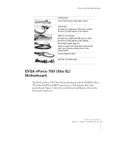
...parts. I/O Shield Installs in the chassis to a new chassis. Be sure to the EVGA Corporation January 11, 2008 | DU-03751-001_v01 4 EVGA nForce 790i Ultra SLI Motherboard This PCI Express motherboard contains the NVIDIA nForce 790i Ultra SLI SPP and MCP and is missing or damaged, ...contact your reseller. Unpacking and Parts Descriptions Unpacking The EVGA nForce 790i Ultra SLI motherboard comes with all the necessary cables for adding a motherboard to block radio frequency transmissions, protect internet components from dust and foreign objects and aids...
...parts. I/O Shield Installs in the chassis to a new chassis. Be sure to the EVGA Corporation January 11, 2008 | DU-03751-001_v01 4 EVGA nForce 790i Ultra SLI Motherboard This PCI Express motherboard contains the NVIDIA nForce 790i Ultra SLI SPP and MCP and is missing or damaged, ...contact your reseller. Unpacking and Parts Descriptions Unpacking The EVGA nForce 790i Ultra SLI motherboard comes with all the necessary cables for adding a motherboard to block radio frequency transmissions, protect internet components from dust and foreign objects and aids...
User Manual
Page 16
... a single drive to the motherboard Comm2 Bracket Cable IDE-ATA 133 HDD Cable EVGA nForce 790i Ultra SLI Motherboard The EVGA nForce 790i Ultra SLI motherboard with the NVIDIA nForce 790i Ultra SLI SPP and MCP processors is a PCI Express, SLI-ready motherboard. EVGA Corporation January 11, 2008 |... DU-03751-001_v01 5 USB 2.0 4-Port Cable Provides four additional USB ports to either the front or back panels of the chassis. nForce 790i SLI Motherboard motherboard. 2-Port SATA Power Cable (Qty Three)...
... a single drive to the motherboard Comm2 Bracket Cable IDE-ATA 133 HDD Cable EVGA nForce 790i Ultra SLI Motherboard The EVGA nForce 790i Ultra SLI motherboard with the NVIDIA nForce 790i Ultra SLI SPP and MCP processors is a PCI Express, SLI-ready motherboard. EVGA Corporation January 11, 2008 |... DU-03751-001_v01 5 USB 2.0 4-Port Cable Provides four additional USB ports to either the front or back panels of the chassis. nForce 790i SLI Motherboard motherboard. 2-Port SATA Power Cable (Qty Three)...

User Manual
Page 18
.../link/Activity • Green/Light Up/Blink = 1000 Mbps/Link/Activity Figure 2. PS/2 Keyboard Port 3. eSATA 6. USB 2.0 ports (SIX) 7. 1394a (Firewire) Port 8. Chassis Backpanel Connectors EVGA Corporation January 11, 2008 | DU-03751-001_v01 7 Coaxial SPDIF 4. PS/2 Mouse Port 2. SPDIF output 5. nForce 790i SLI...
.../link/Activity • Green/Light Up/Blink = 1000 Mbps/Link/Activity Figure 2. PS/2 Keyboard Port 3. eSATA 6. USB 2.0 ports (SIX) 7. 1394a (Firewire) Port 8. Chassis Backpanel Connectors EVGA Corporation January 11, 2008 | DU-03751-001_v01 7 Coaxial SPDIF 4. PS/2 Mouse Port 2. SPDIF output 5. nForce 790i SLI...

User Manual
Page 19
...CPU ¾ Installing the CPU fan ¾ Installing the memory ‰ Installing the motherboard ‰ Connecting cables and setting switches Safety Instructions To reduce the risk of the motherboard. Remember to remove power from your computer by disconnecting the AC main source before removing ...or installing any equipment from/to the computer chassis. EVGA Corporation January 11, 2008 | DU-03751-001_v01 8 Hardware...
...CPU ¾ Installing the CPU fan ¾ Installing the memory ‰ Installing the motherboard ‰ Connecting cables and setting switches Safety Instructions To reduce the risk of the motherboard. Remember to remove power from your computer by disconnecting the AC main source before removing ...or installing any equipment from/to the computer chassis. EVGA Corporation January 11, 2008 | DU-03751-001_v01 8 Hardware...

User Manual
Page 20
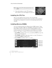
... cover from the socket. 2. Align the notches in the box does not contain a CPU or memory. There is a protective socket cover on the CPU EVGA Corporation January 11, 2008 | DU-03751-001_v01 9 Hold the processor only by the edges. Unhook the socket lever by pushing down into the socket Align...on the socket. 6. Lower the processor straight down and away from the load plate. 4. You need to purchase these to install the CPU onto the motherboard. 1. Installing the CPU Be very careful when handling the CPU. Make sure not to store it. 5. It is no CPU installed. 3.
... cover from the socket. 2. Align the notches in the box does not contain a CPU or memory. There is a protective socket cover on the CPU EVGA Corporation January 11, 2008 | DU-03751-001_v01 9 Hold the processor only by the edges. Unhook the socket lever by pushing down into the socket Align...on the socket. 6. Lower the processor straight down and away from the load plate. 4. You need to purchase these to install the CPU onto the motherboard. 1. Installing the CPU Be very careful when handling the CPU. Make sure not to store it. 5. It is no CPU installed. 3.
User Manual
Page 21
... the socket lever. CPU side DIMM Slot 0 DIMM Slot 2 DIMM Slot 1 DIMM Slot 3 Card-edge EVGA Corporation 10 January 11, 2008 | DU-03751-001_v01 Follow the instruction that came with this motherboard. Be sure that can install the DIMM into slot 0. Use the following the recommendations for installing memory. (... memory bank populated to not have the DIMMs in the socket. 7. The idea is to ensure normal operation. Installing Memory DIMMs Your new motherboard has four 240-pin slots for x8 and x16 devices. These slots support 256 Mb, 512 Mb and 1 Gb DDR3 technologies for DDR3 memory....
... the socket lever. CPU side DIMM Slot 0 DIMM Slot 2 DIMM Slot 1 DIMM Slot 3 Card-edge EVGA Corporation 10 January 11, 2008 | DU-03751-001_v01 Follow the instruction that came with this motherboard. Be sure that can install the DIMM into slot 0. Use the following the recommendations for installing memory. (... memory bank populated to not have the DIMMs in the socket. 7. The idea is to ensure normal operation. Installing Memory DIMMs Your new motherboard has four 240-pin slots for x8 and x16 devices. These slots support 256 Mb, 512 Mb and 1 Gb DDR3 technologies for DDR3 memory....

User Manual
Page 23
... the I /O shield from the chassis supplier. The plastic clips at both sides of installing the motherboard into the chassis. Align the memory module to obtain the proper size from the inside of the DIMM slot. EVGA Corporation 12 January 11, 2008 | DU-03751-001_v01 It is normally easier to ensure the component...
... the I /O shield from the chassis supplier. The plastic clips at both sides of installing the motherboard into the chassis. Align the memory module to obtain the proper size from the inside of the DIMM slot. EVGA Corporation 12 January 11, 2008 | DU-03751-001_v01 It is normally easier to ensure the component...

User Manual
Page 24
...stud to prevent the possibility of a short circuit. Ensure that do not align with a mounting hole on the motherboard. Hardware Installation Securing the Motherboard into the Chassis Most computer chassis have a base with the chassis vents according to the fan assembly instruction. 5.... (PWR2) ‰ Internal Headers ¾ Front panel ¾ IEEE 1394a ¾ USB Headers ¾ Audio EVGA Corporation January 11, 2008 | DU-03751-001_v01 13 Carefully place the motherboard onto the studs/spacers located inside the chassis. 2. Align the mounting holes with a minimum of nine (9) spacers. ...
...stud to prevent the possibility of a short circuit. Ensure that do not align with a mounting hole on the motherboard. Hardware Installation Securing the Motherboard into the Chassis Most computer chassis have a base with the chassis vents according to the fan assembly instruction. 5.... (PWR2) ‰ Internal Headers ¾ Front panel ¾ IEEE 1394a ¾ USB Headers ¾ Audio EVGA Corporation January 11, 2008 | DU-03751-001_v01 13 Carefully place the motherboard onto the studs/spacers located inside the chassis. 2. Align the mounting holes with a minimum of nine (9) spacers. ...

User Manual
Page 25
... settings See Figure 1 on page 6 to locate the connectors and jumpers referenced in either of the following procedure. Power Connections To support 3-way SLI, this motherboard has the following specific power supply requirements: ‰ Minimum 1000 W peak power ‰ Six PCI-E power connectors configured in the following configurations (see Figure ...3): ¾ Four 6-pin (3x2) and two 8-pin (4x2) PCI-E power connectors or ¾ Six 6-pin (3x2) PCI-E power connectors 8-pin (4x2) PCT-E Connector EVGA Corporation 14 January 11, 2008 | DU-03751-001_v01 6-pin (3x2) PCI-E connector
... settings See Figure 1 on page 6 to locate the connectors and jumpers referenced in either of the following procedure. Power Connections To support 3-way SLI, this motherboard has the following specific power supply requirements: ‰ Minimum 1000 W peak power ‰ Six PCI-E power connectors configured in the following configurations (see Figure ...3): ¾ Four 6-pin (3x2) and two 8-pin (4x2) PCI-E power connectors or ¾ Six 6-pin (3x2) PCI-E power connectors 8-pin (4x2) PCT-E Connector EVGA Corporation 14 January 11, 2008 | DU-03751-001_v01 6-pin (3x2) PCI-E connector

User Manual
Page 26
... connector Plug power cable from system power supply to cover all the expansion cards you power requirements are properly aligned with the connector on the motherboard. PWR1 Motherboard Connector PWR1 Pin Assignments Connector 24 12 Pin Signal 1 13 2 3 4 5 1 6 7 8 +3.3V +3.3V GND +5V GND +5V GND PWROK Pin Signal 13 +3.3V 14 -12V...
... connector Plug power cable from system power supply to cover all the expansion cards you power requirements are properly aligned with the connector on the motherboard. PWR1 Motherboard Connector PWR1 Pin Assignments Connector 24 12 Pin Signal 1 13 2 3 4 5 1 6 7 8 +3.3V +3.3V GND +5V GND +5V GND PWROK Pin Signal 13 +3.3V 14 -12V...
