
User Manual
Page 4
... Table of Contents Before You Begin...ix Parts NOT in the Kit ix Intentions of the Kit x EVGA nForce 790i Motherboard 1 Motherboard Specifications 1 Unpacking and Parts Descriptions 4 Unpacking ...4 Equipment ...4 EVGA nForce 790i Ultra SLI Motherboard 5 Hardware Installation 8 Safety Instructions 8 Preparing the Motherboard 9 Installing the CPU 9 Installing the CPU Fan 10 Installing Memory ...the Chassis 13 Connecting Cables and Setting Switches 13 Power Connections 14 24-pin ATX Power (PWR1 15 8-pin ATX 12V Power (PWR2 16 EVGA Corporation January 11, 2008 | DU-03751-001_v01 iii
... Table of Contents Before You Begin...ix Parts NOT in the Kit ix Intentions of the Kit x EVGA nForce 790i Motherboard 1 Motherboard Specifications 1 Unpacking and Parts Descriptions 4 Unpacking ...4 Equipment ...4 EVGA nForce 790i Ultra SLI Motherboard 5 Hardware Installation 8 Safety Instructions 8 Preparing the Motherboard 9 Installing the CPU 9 Installing the CPU Fan 10 Installing Memory ...the Chassis 13 Connecting Cables and Setting Switches 13 Power Connections 14 24-pin ATX Power (PWR1 15 8-pin ATX 12V Power (PWR2 16 EVGA Corporation January 11, 2008 | DU-03751-001_v01 iii
User Manual
Page 5
nForce 790i Ultra SLI Motherboard Connecting IDE Hard Disk Drives 16 Connecting Serial ATA Cables 18 Connecting Internal Headers 19 Front Panel Header 19 IEEE 1394a...20 USB Headers ... Channel and SATA Channel 34 Drive A...37 Halt On ...37 Memory ...38 Advanced BIOS Features 39 Removable Device Priority 40 Hard Disk Boot Priority 40 EVGA Corporation iv January 11, 2008 | DU-03751-001_v01
nForce 790i Ultra SLI Motherboard Connecting IDE Hard Disk Drives 16 Connecting Serial ATA Cables 18 Connecting Internal Headers 19 Front Panel Header 19 IEEE 1394a...20 USB Headers ... Channel and SATA Channel 34 Drive A...37 Halt On ...37 Memory ...38 Advanced BIOS Features 39 Removable Device Priority 40 Hard Disk Boot Priority 40 EVGA Corporation iv January 11, 2008 | DU-03751-001_v01
User Manual
Page 7
nForce 790i Ultra SLI Motherboard HD Audio...62 IDE HDD Block Mode 62 Onboard FDC Controller 63 Onboard Serial Port 1 63 Power Management Setup Menu 63 ACPI Function ...64 ... Software 75 NVIDIA Performance Group of NVIDIA Control Panel 76 Device Settings 77 Current Hardware Settings 78 Dynamic BIOS Access 85 View System Information 86 EVGA Corporation vi January 11, 2008 | DU-03751-001_v01
nForce 790i Ultra SLI Motherboard HD Audio...62 IDE HDD Block Mode 62 Onboard FDC Controller 63 Onboard Serial Port 1 63 Power Management Setup Menu 63 ACPI Function ...64 ... Software 75 NVIDIA Performance Group of NVIDIA Control Panel 76 Device Settings 77 Current Hardware Settings 78 Dynamic BIOS Access 85 View System Information 86 EVGA Corporation vi January 11, 2008 | DU-03751-001_v01
User Manual
Page 10
..., Intel Core 2 Quad, Intel Core 2 Duo Pentium EE, Pentium D, Pentium ‰ Cooling fan for your new EVGA a nForce® 790i Ultra SLI motherboard. If you have two GPUs in an SLI configuration, you have three GPUs in the Kit This kit contains all the hardware necessary to install each of the... parts listed so you are assuming you will need a minimum of a 500 W power supply. EVGA Corporation January 11...
..., Intel Core 2 Quad, Intel Core 2 Duo Pentium EE, Pentium D, Pentium ‰ Cooling fan for your new EVGA a nForce® 790i Ultra SLI motherboard. If you have two GPUs in an SLI configuration, you have three GPUs in the Kit This kit contains all the hardware necessary to install each of the... parts listed so you are assuming you will need a minimum of a 500 W power supply. EVGA Corporation January 11...

User Manual
Page 11
When replacing a motherboard in the kit. EVGA Corporation x January 11, 2008 | DU-03751-001_v01 If however, you are building a PC, you will use most of the cables provided in a PC cabinet, you will not need to install the motherboard into a PC cabinet. nForce 790i Ultra SLI Motherboard Intentions of the cables. If you are replacing a motherboard, you will need many of the Kit This kit provides you with the motherboard and all connecting cables necessary to reinstall an operating system even though the current drives have an operating system.
When replacing a motherboard in the kit. EVGA Corporation x January 11, 2008 | DU-03751-001_v01 If however, you are building a PC, you will use most of the cables provided in a PC cabinet, you will not need to install the motherboard into a PC cabinet. nForce 790i Ultra SLI Motherboard Intentions of the cables. If you are replacing a motherboard, you will need many of the Kit This kit provides you with the motherboard and all connecting cables necessary to reinstall an operating system even though the current drives have an operating system.
User Manual
Page 12
... NVIDIA GeForce graphics cards, you for enhanced system performance. EVGA nForce 790i Ultra SLI Motherboard Thank you get innovative NVIDIA SLI Technology for buying the EVGA NFORCE 790i Ultra SLI Motherboard. Supports up to 8 GBs DDR3 memories. ‰ Ten USB 2.0 Ports ¾ Supports hot plug ¾ Ten USB 2.0 ports (six rear panel ports, four onboard ...
... NVIDIA GeForce graphics cards, you for enhanced system performance. EVGA nForce 790i Ultra SLI Motherboard Thank you get innovative NVIDIA SLI Technology for buying the EVGA NFORCE 790i Ultra SLI Motherboard. Supports up to 8 GBs DDR3 memories. ‰ Ten USB 2.0 Ports ¾ Supports hot plug ¾ Ten USB 2.0 ports (six rear panel ports, four onboard ...
User Manual
Page 13
... PCI slots ¾ One PCI Express x1 slot ¾ Three PCI Express x16 Graphics slots EVGA Corporation 2 January 11, 2008 | DU-03751-001_v01 depends on suspend), S3 (suspend to RAM), S4 (Suspend to disk - nForce 790i Ultra SLI Motherboard ‰ Onboard Serial ATA II ¾ 300MBps data transfer rate ¾ Six Serial ATA...
... PCI slots ¾ One PCI Express x1 slot ¾ Three PCI Express x16 Graphics slots EVGA Corporation 2 January 11, 2008 | DU-03751-001_v01 depends on suspend), S3 (suspend to RAM), S4 (Suspend to disk - nForce 790i Ultra SLI Motherboard ‰ Onboard Serial ATA II ¾ 300MBps data transfer rate ¾ Six Serial ATA...

User Manual
Page 15
... damaged, contact your reseller. If you are RoHS-compliant (lead-free) parts. EVGA nForce 790i Ultra SLI Motherboard This PCI Express motherboard contains the NVIDIA nForce 790i Ultra SLI SPP and MCP and is SLI-ready. Unpacking and Parts Descriptions Unpacking The EVGA nForce 790i Ultra SLI motherboard comes with all the necessary cables for adding a motherboard to block...
... damaged, contact your reseller. If you are RoHS-compliant (lead-free) parts. EVGA nForce 790i Ultra SLI Motherboard This PCI Express motherboard contains the NVIDIA nForce 790i Ultra SLI SPP and MCP and is SLI-ready. Unpacking and Parts Descriptions Unpacking The EVGA nForce 790i Ultra SLI motherboard comes with all the necessary cables for adding a motherboard to block...
User Manual
Page 16
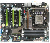
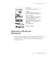
nForce 790i SLI Motherboard motherboard. 2-Port SATA Power Cable (Qty Three) 1394 Cable Provides two additional 1394 ports to either the front or back panels of the chassis. Figure 1 shows the motherboard and Figures 2 shows the back panel connectors. EVGA Corporation January 11, 2008 | DU-03751-001_v01 5 USB ... Serial ATA protocol and each one connects a single drive to the motherboard Comm2 Bracket Cable IDE-ATA 133 HDD Cable EVGA nForce 790i Ultra SLI Motherboard The EVGA nForce 790i Ultra SLI motherboard with the NVIDIA nForce 790i Ultra SLI SPP and MCP processors is a PCI Express...
nForce 790i SLI Motherboard motherboard. 2-Port SATA Power Cable (Qty Three) 1394 Cable Provides two additional 1394 ports to either the front or back panels of the chassis. Figure 1 shows the motherboard and Figures 2 shows the back panel connectors. EVGA Corporation January 11, 2008 | DU-03751-001_v01 5 USB ... Serial ATA protocol and each one connects a single drive to the motherboard Comm2 Bracket Cable IDE-ATA 133 HDD Cable EVGA nForce 790i Ultra SLI Motherboard The EVGA nForce 790i Ultra SLI motherboard with the NVIDIA nForce 790i Ultra SLI SPP and MCP processors is a PCI Express...
User Manual
Page 21
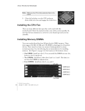
... plate over the CPU and press down while you fan assembly. There must be used with you close and engage the socket lever. nForce 790i Ultra SLI Motherboard Note: Make sure the CPU is fully seated and level in adjacent slots. ‰ Four DIMMS: Install into slots 0, 1, 2, and 3.... CPU side DIMM Slot 0 DIMM Slot 2 DIMM Slot 1 DIMM Slot 3 Card-edge EVGA Corporation 10 January 11, 2008 | DU-03751-001_v01 Follow the instruction that the fan orientation is correct for the location of the memory slots.) ‰...
... plate over the CPU and press down while you fan assembly. There must be used with you close and engage the socket lever. nForce 790i Ultra SLI Motherboard Note: Make sure the CPU is fully seated and level in adjacent slots. ‰ Four DIMMS: Install into slots 0, 1, 2, and 3.... CPU side DIMM Slot 0 DIMM Slot 2 DIMM Slot 1 DIMM Slot 3 Card-edge EVGA Corporation 10 January 11, 2008 | DU-03751-001_v01 Follow the instruction that the fan orientation is correct for the location of the memory slots.) ‰...

User Manual
Page 23
... or to lock into place and for the chassis covers to secure the motherboard and then make sure the CPU Fan assembly is installed properly. 1. EVGA Corporation 12 January 11, 2008 | DU-03751-001_v01 Also make all the connections. Before installing the motherboard, install the I /O shield that is only one ...obtain the proper size from the inside of installing the motherboard into the chassis depends on the covers. Determine if it fits securely. nForce 790i Ultra SLI Motherboard Use the following procedure to the DIMM slot, and insert the module vertically into the DIMM slot.
... or to lock into place and for the chassis covers to secure the motherboard and then make sure the CPU Fan assembly is installed properly. 1. EVGA Corporation 12 January 11, 2008 | DU-03751-001_v01 Also make all the connections. Before installing the motherboard, install the I /O shield that is only one ...obtain the proper size from the inside of installing the motherboard into the chassis depends on the covers. Determine if it fits securely. nForce 790i Ultra SLI Motherboard Use the following procedure to the DIMM slot, and insert the module vertically into the DIMM slot.
User Manual
Page 25
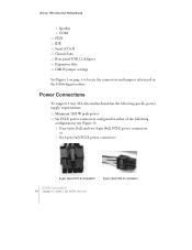
... Ultra SLI Motherboard ¾ Speaker ¾ COM ‰ FDD ‰ IDE ‰ Serial ATA II ‰ Chassis Fans ‰ Rear panel USB 2.0 Adapter ‰ Expansion slots ‰ CMOS jumper settings See Figure 1 on page 6 to locate the connectors and jumpers referenced in either of the following procedure. Power Connections To support 3-way SLI...
... Ultra SLI Motherboard ¾ Speaker ¾ COM ‰ FDD ‰ IDE ‰ Serial ATA II ‰ Chassis Fans ‰ Rear panel USB 2.0 Adapter ‰ Expansion slots ‰ CMOS jumper settings See Figure 1 on page 6 to locate the connectors and jumpers referenced in either of the following procedure. Power Connections To support 3-way SLI...
User Manual
Page 27
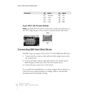
Connect the black connector (the cable with a single connector) to the Ultra ATA master device. 3. nForce 790i Ultra SLI Motherboard Connector Pin Signal 9 +5V_AUX 10 +12V 11 +12V 12 +3.3V Pin Signal 21 +5V 22 +5V 23 +5V 24 GND 8-pin ATX 12V Power (... disk documentation for the jumper settings. Connect the blue connector (the cable end with the two closely spaced black and gray connectors) to the motherboard. 2. EVGA Corporation 16 January 11, 2008 | DU-03751-001_v01 Backpanel connector edge GND 1 4 5 8 12V Connecting IDE Hard Disk Drives The IDE connector supports...
Connect the black connector (the cable with a single connector) to the Ultra ATA master device. 3. nForce 790i Ultra SLI Motherboard Connector Pin Signal 9 +5V_AUX 10 +12V 11 +12V 12 +3.3V Pin Signal 21 +5V 22 +5V 23 +5V 24 GND 8-pin ATX 12V Power (... disk documentation for the jumper settings. Connect the blue connector (the cable end with the two closely spaced black and gray connectors) to the motherboard. 2. EVGA Corporation 16 January 11, 2008 | DU-03751-001_v01 Backpanel connector edge GND 1 4 5 8 12V Connecting IDE Hard Disk Drives The IDE connector supports...
User Manual
Page 29
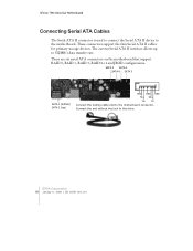
... GND TX+ RX+ TX- Connect the locking cable end to the drive. The current Serial ATA II interface allows up to the motherboard. nForce 790i Ultra SLI Motherboard Connecting Serial ATA Cables The Serial ATA II connector is used to connect the Serial ATA II device to 300MB/s data transfer rate...
... GND TX+ RX+ TX- Connect the locking cable end to the drive. The current Serial ATA II interface allows up to the motherboard. nForce 790i Ultra SLI Motherboard Connecting Serial ATA Cables The Serial ATA II connector is used to connect the Serial ATA II device to 300MB/s data transfer rate...

User Manual
Page 31
... 9 4 8 7 6 5 5 4 3 6 2 1 7 8 9 Signal TPA+ TPAGND GND TPB+ TPB+12V +12V Empty Card Edge EVGA Corporation 20 January 11, 2008 | DU-03751-001_v01 Connect the two ends of your chassis (not all chassis are equipped with the front panel option). 2. nForce 790i Ultra SLI Motherboard Table 2. Table 3. Secure the bracket to either the front or rear...
... 9 4 8 7 6 5 5 4 3 6 2 1 7 8 9 Signal TPA+ TPAGND GND TPB+ TPB+12V +12V Empty Card Edge EVGA Corporation 20 January 11, 2008 | DU-03751-001_v01 Connect the two ends of your chassis (not all chassis are equipped with the front panel option). 2. nForce 790i Ultra SLI Motherboard Table 2. Table 3. Secure the bracket to either the front or rear...
User Manual
Page 33
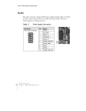
The front Audio supports re-tasking function. Front Audio Connector Connector Front Audio Connector 10 9 8 7 6 5 4 3 2 1 Pin Signal 1 PORT1_L 2 AUD_GND 3 PORT1_R 4 PRECENCE_J 5 PORT2_R 6 SENSE1_RETURN 7 SENSE_SEND 8 Empty 9 PORT2_L 10 SENSE2_RETURN Card Edge EVGA Corporation 22 January 11, 2008 | DU-03751-001_v01 nForce 790i Ultra SLI Motherboard Audio The audio connector supports HD audio standard and provides two kinds of audio output choices: the Front Audio, the Rear Audio. Table 5.
The front Audio supports re-tasking function. Front Audio Connector Connector Front Audio Connector 10 9 8 7 6 5 4 3 2 1 Pin Signal 1 PORT1_L 2 AUD_GND 3 PORT1_R 4 PRECENCE_J 5 PORT2_R 6 SENSE1_RETURN 7 SENSE_SEND 8 Empty 9 PORT2_L 10 SENSE2_RETURN Card Edge EVGA Corporation 22 January 11, 2008 | DU-03751-001_v01 nForce 790i Ultra SLI Motherboard Audio The audio connector supports HD audio standard and provides two kinds of audio output choices: the Front Audio, the Rear Audio. Table 5.
User Manual
Page 34
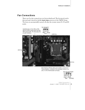
.... Hardware Installation Fan Connections There are automatically turned off after the system enters S3, S4 and S5 mode. CPU Fan Connector 4 3 2 GND SENSE PWR CONTROL EVGA Corporation January 11, 2008 | DU-03751-001_v01 23 The fans are five fan connections on the motherboard. The fans plug into a 3-pin connector. 3 21 GND... can be detected and viewed in the PC Health Status section of the CMOS Setup. Connect a 3-pin connector to pins 1, 2, and 3 on the nForce 790i Ultra SLI MCP to draw heat from the MCP and the SPP.
.... Hardware Installation Fan Connections There are automatically turned off after the system enters S3, S4 and S5 mode. CPU Fan Connector 4 3 2 GND SENSE PWR CONTROL EVGA Corporation January 11, 2008 | DU-03751-001_v01 23 The fans are five fan connections on the motherboard. The fans plug into a 3-pin connector. 3 21 GND... can be detected and viewed in the PC Health Status section of the CMOS Setup. Connect a 3-pin connector to pins 1, 2, and 3 on the nForce 790i Ultra SLI MCP to draw heat from the MCP and the SPP.
User Manual
Page 35
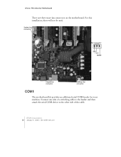
nForce 790i Ultra SLI Motherboard There are three more fan connectors on the motherboard. EVGA Corporation 24 January 11, 2008 | DU-03751-001_v01 Connect one side of a switching cable to the header and then attach the serial COM device to the other side of the cable. For this installation, these will not be used. System fan connector Fan Connector 3 2 GND +12V SENSE Chassis fan connector Auxiliary fan connector COM1 The motherboard kit provides an additional serial COM header for your machine.
nForce 790i Ultra SLI Motherboard There are three more fan connectors on the motherboard. EVGA Corporation 24 January 11, 2008 | DU-03751-001_v01 Connect one side of a switching cable to the header and then attach the serial COM device to the other side of the cable. For this installation, these will not be used. System fan connector Fan Connector 3 2 GND +12V SENSE Chassis fan connector Auxiliary fan connector COM1 The motherboard kit provides an additional serial COM header for your machine.
User Manual
Page 36
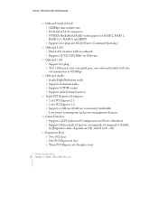
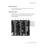
For a full list of PCI Express x16 graphics card supported by this motherboard, go to www.nvidia.com/estore. 1 2 3 4 5 6 5 1 - PCIe x1 slots 6 - Hardware Installation FDD Connector The motherboard supports a standard 360K, 720K, 1.2M, 1.44m, and a 2.88M floppy disk drive (FDD). PCIe x16 slot 1 (Primary) EVGA Corporation January 11, 2008 | DU-03751-001_v01 25 PCIe x16 slot 2 3 - PCI slot 2 4 - PCIe x16 slot 3 5 - Expansion Slots The EVGA nForce 790i Ultra SLI motherboard contains seven expansion slots, five PCI Express slots and two PCI slots. PCI slot 1 2 -
For a full list of PCI Express x16 graphics card supported by this motherboard, go to www.nvidia.com/estore. 1 2 3 4 5 6 5 1 - PCIe x1 slots 6 - Hardware Installation FDD Connector The motherboard supports a standard 360K, 720K, 1.2M, 1.44m, and a 2.88M floppy disk drive (FDD). PCIe x16 slot 1 (Primary) EVGA Corporation January 11, 2008 | DU-03751-001_v01 25 PCIe x16 slot 2 3 - PCI slot 2 4 - PCIe x16 slot 3 5 - Expansion Slots The EVGA nForce 790i Ultra SLI motherboard contains seven expansion slots, five PCI Express slots and two PCI slots. PCI slot 1 2 -

User Manual
Page 37
EVGA Corporation 26 January 11, 2008 | DU-03751-001_v01 The x1 slots provide 250 MB/sec bandwidth....it could cause a short across the pins. The bandwidth of this motherboard supports three PCI-Express graphics cards using NVIDIA's SLI technology with the screw used to 4GB/sec (8GB/sec concurrent). Secure the card's metal bracket to the chassis back... a LAN card, USB card, SCSI card and other cards that are designed to hold the blank cover. nForce 790i Ultra SLI Motherboard PCI Slots The two PCI slots support many expansion cards such as a modem or LAN card. PCI Express x16 ...
EVGA Corporation 26 January 11, 2008 | DU-03751-001_v01 The x1 slots provide 250 MB/sec bandwidth....it could cause a short across the pins. The bandwidth of this motherboard supports three PCI-Express graphics cards using NVIDIA's SLI technology with the screw used to 4GB/sec (8GB/sec concurrent). Secure the card's metal bracket to the chassis back... a LAN card, USB card, SCSI card and other cards that are designed to hold the blank cover. nForce 790i Ultra SLI Motherboard PCI Slots The two PCI slots support many expansion cards such as a modem or LAN card. PCI Express x16 ...