User Manual
Page 21
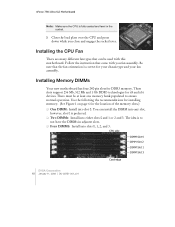
Close the load plate over the CPU and press down while you fan assembly. The idea is to ensure normal operation. These slots support 256 Mb, 512 Mb and 1 Gb DDR3 technologies for your chassis type and your fan assembly. There must be used with you close and engage ...the socket lever. Be sure that the fan orientation is correct for x8 and x16 devices. CPU side DIMM Slot 0 DIMM Slot 2 DIMM Slot 1 DIMM Slot 3 Card-edge EVGA Corporation 10 January 11, 2008 | DU-03751-001_v01 Installing Memory DIMMs Your new motherboard has four 240-pin slots...
Close the load plate over the CPU and press down while you fan assembly. The idea is to ensure normal operation. These slots support 256 Mb, 512 Mb and 1 Gb DDR3 technologies for your chassis type and your fan assembly. There must be used with you close and engage ...the socket lever. Be sure that the fan orientation is correct for x8 and x16 devices. CPU side DIMM Slot 0 DIMM Slot 2 DIMM Slot 1 DIMM Slot 3 Card-edge EVGA Corporation 10 January 11, 2008 | DU-03751-001_v01 Installing Memory DIMMs Your new motherboard has four 240-pin slots...
User Manual
Page 27
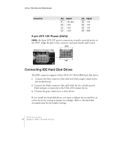
Connect the black connector (the cable with a single connector) to the CPU. Refer to the Ultra ATA master device. 3. Connect the blue connector (the cable end with the two closely spaced black and gray connectors) to the ... 8-pin ATX 12V power connection, is used to provide power to the motherboard. 2. Connect the gray connector to the connector and press firmly until seated. EVGA Corporation 16 January 11, 2008 | DU-03751-001_v01 Align the pins to a slave device. Backpanel connector edge GND 1 4 5 8 12V Connecting IDE Hard Disk Drives The...
Connect the black connector (the cable with a single connector) to the CPU. Refer to the Ultra ATA master device. 3. Connect the blue connector (the cable end with the two closely spaced black and gray connectors) to the ... 8-pin ATX 12V power connection, is used to provide power to the motherboard. 2. Connect the gray connector to the connector and press firmly until seated. EVGA Corporation 16 January 11, 2008 | DU-03751-001_v01 Align the pins to a slave device. Backpanel connector edge GND 1 4 5 8 12V Connecting IDE Hard Disk Drives The...

User Manual
Page 64
...137; CPU Thermal Control Use this function to enable the set limit of the CPUID MaxVal to enable or disable TM1 and TM2 support. Set...CPU Configuration Limit CPUID MaxVal x Intel SpeedStep CPU Thermal Control C1E Enhanced Halt State Execute Disable Bit Virtualization Technology [Disabled] Disabled [Disabled] [Enabled] [Enabled] [Enabled] CPU Core 0 CPU Core 1 x CPU Core 2 x CPU... Core 3 Enabled [Enabled] Disabled Disabled Item Help Main Level `` Set linit CPUID MaxVal to display the CPU Configuration menu. Configuring ...
...137; CPU Thermal Control Use this function to enable the set limit of the CPUID MaxVal to enable or disable TM1 and TM2 support. Set...CPU Configuration Limit CPUID MaxVal x Intel SpeedStep CPU Thermal Control C1E Enhanced Halt State Execute Disable Bit Virtualization Technology [Disabled] Disabled [Disabled] [Enabled] [Enabled] [Enabled] CPU Core 0 CPU Core 1 x CPU Core 2 x CPU... Core 3 Enabled [Enabled] Disabled Disabled Item Help Main Level `` Set linit CPUID MaxVal to display the CPU Configuration menu. Configuring ...

User Manual
Page 65
EVGA Corporation 54 January 11, 2008 | DU-03751-001_v01 nForce 790i Ultra SLI Motherboard ¾ Disable Disable support for TM1 and TM2. ¾ TM1 Only The CPU is thermally throttled by cutting active processor clock cycles. ¾ TM2 Only Thermal throttling is achieved by reducing the CPU multiplier and CPU... core voltage. ¾ TM1 & TM2 Enables support for both TM1 and TM2. ‰ C1E Enhanced Halt State Enabled, this function is enabled, it ...
EVGA Corporation 54 January 11, 2008 | DU-03751-001_v01 nForce 790i Ultra SLI Motherboard ¾ Disable Disable support for TM1 and TM2. ¾ TM1 Only The CPU is thermally throttled by cutting active processor clock cycles. ¾ TM2 Only Thermal throttling is achieved by reducing the CPU multiplier and CPU... core voltage. ¾ TM1 & TM2 Enables support for both TM1 and TM2. ‰ C1E Enhanced Halt State Enabled, this function is enabled, it ...

User Manual
Page 114
... Previous Power State SLAM table Hardware Workarounds Restore, and exit NVMM Memory Test ERROR handler End of Table Invalid APIC ID CPU Identify/Init failed North Bridge not supported South Bridge not supported No DIMMs present Invalid DIMM types, SDR/DDR Different voltage levels Invalid REFRESH Rate Invalide memory geometry Slam Engine error...
... Previous Power State SLAM table Hardware Workarounds Restore, and exit NVMM Memory Test ERROR handler End of Table Invalid APIC ID CPU Identify/Init failed North Bridge not supported South Bridge not supported No DIMMs present Invalid DIMM types, SDR/DDR Different voltage levels Invalid REFRESH Rate Invalide memory geometry Slam Engine error...
