
User Guide
Page 2
EVGA Z68/P67 Motherboard
EVGA Z68/P67 Motherboard

User Guide
Page 3
EVGA Z68/P67 Motherboard Table of Contents
EVGA Z68/P67 Motherboard Table of Contents

User Guide
Page 4
EVGA Z68/P67 Motherboard
EVGA Z68/P67 Motherboard

User Guide
Page 5
EVGA Z68/P67 Motherboard Thank you for the performance you demand, delivered when you ever have any issues or questions. As always this board comes with the added bonus of the new Intel Z68/P67 chipset with native support for SATA III/6G for purchasing the EVGA Z68/P67 Motherboard. This board is based off of EVGA's industry leading 24/7 technical support in case you need it.
EVGA Z68/P67 Motherboard Thank you for the performance you demand, delivered when you ever have any issues or questions. As always this board comes with the added bonus of the new Intel Z68/P67 chipset with native support for SATA III/6G for purchasing the EVGA Z68/P67 Motherboard. This board is based off of EVGA's industry leading 24/7 technical support in case you need it.

User Guide
Page 6
... in a PC case, you will need many of supported CPU's on this motherboard, please visit http://www.evga.com/support/motherboard/. If however, you are building a PC, you with the motherboard and all connecting cables necessary to reinstall an operating system even though the current ...allow for proper system functionality. When replacing a motherboard in the kit. For a full list of the cables. EVGA Z68/P67 Motherboard This kit contains all the necessary parts needed to install and connect your new EVGA Z68/P67 Motherboard. However, it does not contain the following items...
... in a PC case, you will need many of supported CPU's on this motherboard, please visit http://www.evga.com/support/motherboard/. If however, you are building a PC, you with the motherboard and all connecting cables necessary to reinstall an operating system even though the current ...allow for proper system functionality. When replacing a motherboard in the kit. For a full list of the cables. EVGA Z68/P67 Motherboard This kit contains all the necessary parts needed to install and connect your new EVGA Z68/P67 Motherboard. However, it does not contain the following items...
User Guide
Page 7
EVGA Z68/P67 Motherboard Size EATX form factor of DDR3 memory. USB 2.0 Ports Supports hot plug Supports wake-up from S1 and S3 mode Supports USB 2.0 protocol ...
EVGA Z68/P67 Motherboard Size EATX form factor of DDR3 memory. USB 2.0 Ports Supports hot plug Supports wake-up from S1 and S3 mode Supports USB 2.0 protocol ...

User Guide
Page 8
depends on suspend), S3 (suspend to RAM), S4 (Suspend to disk - off) Expansion Slots PCI-E x1 slots PCI-E x8/x16 slots EVGA Z68/P67 Motherboard SATA ports up to 3.0 Gb/s (300 M/s) data transfer rate SATA ports up to 6.0 Gb/s (600 M/s) data transfer rate Support for RAID 0, RAID 1, RAID 0+1, RAID5 ...
depends on suspend), S3 (suspend to RAM), S4 (Suspend to disk - off) Expansion Slots PCI-E x1 slots PCI-E x8/x16 slots EVGA Z68/P67 Motherboard SATA ports up to 3.0 Gb/s (300 M/s) data transfer rate SATA ports up to 6.0 Gb/s (600 M/s) data transfer rate Support for RAID 0, RAID 1, RAID 0+1, RAID5 ...

User Guide
Page 9
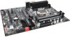
... these cables. The following accessories are included with all the necessary cables for adding a motherboard to a system case. I/O Shield Installs in proper airflow within the chassis. EVGA Z68/P67 Motherboard The EVGA Z68/P67 Motherboard comes with the EVGA Z68/P67 Motherboard: The EVGA Z68/P67 Motherboard This PCI-E motherboard contains the Intel Z68/P67 chipset and is SLI-ready. -
... these cables. The following accessories are included with all the necessary cables for adding a motherboard to a system case. I/O Shield Installs in proper airflow within the chassis. EVGA Z68/P67 Motherboard The EVGA Z68/P67 Motherboard comes with the EVGA Z68/P67 Motherboard: The EVGA Z68/P67 Motherboard This PCI-E motherboard contains the Intel Z68/P67 chipset and is SLI-ready. -
User Guide
Page 10
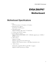
...Model Only) Bridges three (3) graphics cards together which allows for 3-way SLI. - 2-way SLI Bridge Bridges two (2) graphics cards together which allows for 2-way SLI. EVGA Z68/P67 Motherboard - I/O Shield Fan (Optional) Exhausts Air from the IO Shield out of the rear of 2 USB 3.0 ports by Connecting to the... motherboard header. - Attaches to IO Shield. - 2-Port SATA Power Cables Allows a Molex power connector to adapt to a SATA power connector. - 2-Port USB 2.0 / 1394a Firewire Bracket ...
...Model Only) Bridges three (3) graphics cards together which allows for 3-way SLI. - 2-way SLI Bridge Bridges two (2) graphics cards together which allows for 2-way SLI. EVGA Z68/P67 Motherboard - I/O Shield Fan (Optional) Exhausts Air from the IO Shield out of the rear of 2 USB 3.0 ports by Connecting to the... motherboard header. - Attaches to IO Shield. - 2-Port SATA Power Cables Allows a Molex power connector to adapt to a SATA power connector. - 2-Port USB 2.0 / 1394a Firewire Bracket ...
User Guide
Page 11
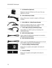
Installation CD Contains drivers and soare needed to setup the motherboard. - User Manual Contains Information needed to properly install and configure your CPU frequency in real time. - ECP Panel (Optional) Allows monitoring of post codes and remote control of PCIe slot disable, voltages and CMOS reset all on one bay mounted panel. - EVGA Z68/P67 Motherboard - EVGauge (Optional) Analog Gauge that represents your EVGA Motherboard.
Installation CD Contains drivers and soare needed to setup the motherboard. - User Manual Contains Information needed to properly install and configure your CPU frequency in real time. - ECP Panel (Optional) Allows monitoring of post codes and remote control of PCIe slot disable, voltages and CMOS reset all on one bay mounted panel. - EVGA Z68/P67 Motherboard - EVGauge (Optional) Analog Gauge that represents your EVGA Motherboard.

User Guide
Page 12
Remember to remove power from your computer by disconnecting the AC main source before removing or installing any equipment from/to the computer chassis. The topics covered in this section are: Preparing the motherboard Installing the CPU Installing the CPU fan Installing the memory Installing the motherboard Connecting cables To reduce the risk of the motherboard. EVGA Z68/P67 Motherboard This section will guide you through the installation of fire, electric shock, and injury, always follow basic safety precautions.
Remember to remove power from your computer by disconnecting the AC main source before removing or installing any equipment from/to the computer chassis. The topics covered in this section are: Preparing the motherboard Installing the CPU Installing the CPU fan Installing the memory Installing the motherboard Connecting cables To reduce the risk of the motherboard. EVGA Z68/P67 Motherboard This section will guide you through the installation of fire, electric shock, and injury, always follow basic safety precautions.

User Guide
Page 13
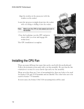
... CPU so for any reason you can replace the cover to install the CPU onto the motherboard: Unhook the socket lever by the edges and do not touch the bottom of the processor. EVGA Z68/P67 Motherboard Be very careful when handling the CPU. Pull the socket lever back and the load plate...
... CPU so for any reason you can replace the cover to install the CPU onto the motherboard: Unhook the socket lever by the edges and do not touch the bottom of the processor. EVGA Z68/P67 Motherboard Be very careful when handling the CPU. Pull the socket lever back and the load plate...
User Guide
Page 14
... holes will be used for Socket 1156 and 1155 heatsinks and are many different fan types that can be used for Socket 775 heatsinks. EVGA Z68/P67 Motherboard Align the notches in the socket. Note: Make sure the CPU is fully seated and level in the processor with your fan assembly. ... chassis type and your fan assembly. The other holes are holes to be used with out tilting or sliding it into the socket with this motherboard. Lower the processor straight down while you close and engage the socket lever. Align notches with notches on the socket. Be sure that there ...
... holes will be used for Socket 1156 and 1155 heatsinks and are many different fan types that can be used for Socket 775 heatsinks. EVGA Z68/P67 Motherboard Align the notches in the socket. Note: Make sure the CPU is fully seated and level in the processor with your fan assembly. ... chassis type and your fan assembly. The other holes are holes to be used with out tilting or sliding it into the socket with this motherboard. Lower the processor straight down while you close and engage the socket lever. Align notches with notches on the socket. Be sure that there ...

User Guide
Page 15
... into : DIMM slots 1 and 3. This slot matches the slot on page for DDR3 memory. Unlock a DIMM slot by pressing the module clips outward. EVGA Z68/P67 Motherboard Your new motherboard has four 240-pin slots for the location of the memory slots.) One DIMM: If using 1 DIMM (Single Channel), install into: DIMM...
... into : DIMM slots 1 and 3. This slot matches the slot on page for DDR3 memory. Unlock a DIMM slot by pressing the module clips outward. EVGA Z68/P67 Motherboard Your new motherboard has four 240-pin slots for the location of the memory slots.) One DIMM: If using 1 DIMM (Single Channel), install into: DIMM...

User Guide
Page 16
...does not fit into place and for ease of installation you are replacing an existing motherboard or working with the vents on the covers. EVGA Z68/P67 Motherboard The sequence of installing the motherboard into place and make sure it would need to obtain the proper size from the ... may want to block radio frequency transmissions, protects internal components from the inside of the chassis. Press the I /O shield and secure the motherboard into case. Use the following procedure to install the I /O shield into a system case depends on the system case being used to install...
...does not fit into place and for ease of installation you are replacing an existing motherboard or working with the vents on the covers. EVGA Z68/P67 Motherboard The sequence of installing the motherboard into place and make sure it would need to obtain the proper size from the ... may want to block radio frequency transmissions, protects internal components from the inside of the chassis. Press the I /O shield and secure the motherboard into case. Use the following procedure to install the I /O shield into a system case depends on the system case being used to install...
User Guide
Page 17
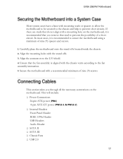
...aligned with mounting studs or spacers to allow the motherboard to be secured to the chassis and help to prevent short circuits. If there are studs that do not align with a mounting hole on the motherboard. EVGA Z68/P67 Motherboard Most system cases have a base with the ...chassis vents according to the fan assembly instruction. 5. Align the connectors to secure the motherboard using a minimum of a short circuit.
...aligned with mounting studs or spacers to allow the motherboard to be secured to the chassis and help to prevent short circuits. If there are studs that do not align with a mounting hole on the motherboard. EVGA Z68/P67 Motherboard Most system cases have a base with the ...chassis vents according to the fan assembly instruction. 5. Align the connectors to secure the motherboard using a minimum of a short circuit.
User Guide
Page 18
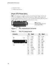
... 13 +3.3V 14 -12V 15 GND 16 PS_ON 17 GND 18 GND 19 GND 20 RSVD 21 +5V 22 +5V 23 +5V 24 GND EVGA Z68/P67 Motherboard Expansion slots CMOS Clear Button PW1 is secure. Firmly plug the power supply cable into the connector and make sure it is... the edge of the board next to PW1 Board edge Figure 1. PW1 connector Plug power cable from system power supply to the DIMM slots. PW1 Motherboard Connector Table 1. Make sure that the power supply cable and pins are properly aligned with the connector on the...
... 13 +3.3V 14 -12V 15 GND 16 PS_ON 17 GND 18 GND 19 GND 20 RSVD 21 +5V 22 +5V 23 +5V 24 GND EVGA Z68/P67 Motherboard Expansion slots CMOS Clear Button PW1 is secure. Firmly plug the power supply cable into the connector and make sure it is... the edge of the board next to PW1 Board edge Figure 1. PW1 connector Plug power cable from system power supply to the DIMM slots. PW1 Motherboard Connector Table 1. Make sure that the power supply cable and pins are properly aligned with the connector on the...

User Guide
Page 19
... physical BIOS chips are to the right of the PC speaker on the lower edge of profiles to the connector and press firmly until seated. EVGA Z68/P67 Motherboard PW12-1 & PW12-2, the 8-pin ATX 12V power connection, is powered on.
... physical BIOS chips are to the right of the PC speaker on the lower edge of profiles to the connector and press firmly until seated. EVGA Z68/P67 Motherboard PW12-1 & PW12-2, the 8-pin ATX 12V power connection, is powered on.
User Guide
Page 20
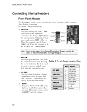
... from No Connect 9 +5V the front panel of the case to these two pins. Note: Some system cases do not have all four cables. EVGA Z68/P67 Motherboard The front panel header on and off . When the system is off rather than using the onboard button. HD_LED Attach the hard disk.... The Power LED indicates the system's status. Pressing Table 2.Front Panel Header Pins the power button on the front panel turns the system on this motherboard is pressed.
... from No Connect 9 +5V the front panel of the case to these two pins. Note: Some system cases do not have all four cables. EVGA Z68/P67 Motherboard The front panel header on and off . When the system is off rather than using the onboard button. HD_LED Attach the hard disk.... The Power LED indicates the system's status. Pressing Table 2.Front Panel Header Pins the power button on the front panel turns the system on this motherboard is pressed.

User Guide
Page 21
IEEE 1394a Connector Pins Connector IEEE 1394a Connector 1 0 9 8 7 6 5 4 3 2 1 Pin 1 2 3 4 5 6 7 8 9 10 Signal TPA+ TPAGND GND TPB+ TPB+12V +12V Empty GND Secure the bracket to either the front or rear panel of the cable(s) to install it. Connect the end of the system case (not all system cases are equipped with the front panel option). Table 3. EVGA Z68/P67 Motherboard The IEEE 1394a expansion cable bracket is provided in the box but if you do not require the additional external connections, you do not need to the IEEE 1394a headers on the motherboard.
IEEE 1394a Connector Pins Connector IEEE 1394a Connector 1 0 9 8 7 6 5 4 3 2 1 Pin 1 2 3 4 5 6 7 8 9 10 Signal TPA+ TPAGND GND TPB+ TPB+12V +12V Empty GND Secure the bracket to either the front or rear panel of the cable(s) to install it. Connect the end of the system case (not all system cases are equipped with the front panel option). Table 3. EVGA Z68/P67 Motherboard The IEEE 1394a expansion cable bracket is provided in the box but if you do not require the additional external connections, you do not need to the IEEE 1394a headers on the motherboard.