
User Guide
Page 5
This board is based off of EVGA's industry leading 24/7 technical support in case you ever have any issues or questions. As always this board comes with the added bonus of the new Intel Z68/P67 chipset with native support for SATA III/6G for the performance you demand, delivered when you for purchasing the EVGA Z68/P67 Motherboard. EVGA Z68/P67 Motherboard Thank you need it.
This board is based off of EVGA's industry leading 24/7 technical support in case you ever have any issues or questions. As always this board comes with the added bonus of the new Intel Z68/P67 chipset with native support for SATA III/6G for the performance you demand, delivered when you for purchasing the EVGA Z68/P67 Motherboard. EVGA Z68/P67 Motherboard Thank you need it.

User Guide
Page 6
... current Hard Disk Drive may already have purchased all the necessary parts needed to allow for the processor PCI Express Graphics Card Power Supply EVGA assumes you will need many of the cables. If you are replacing a motherboard, you will use most of supported CPU's on this motherboard, please visit http://www.evga.com/support/motherboard/. If however, you are building a PC, you with the motherboard and all connecting cables necessary to install and connect...
... current Hard Disk Drive may already have purchased all the necessary parts needed to allow for the processor PCI Express Graphics Card Power Supply EVGA assumes you will need many of the cables. If you are replacing a motherboard, you will use most of supported CPU's on this motherboard, please visit http://www.evga.com/support/motherboard/. If however, you are building a PC, you with the motherboard and all connecting cables necessary to install and connect...
User Guide
Page 7
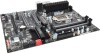
... Microprocessor support Intel Socket 1155 Processor Operating systems: Supports Windows XP/Vista/7 32 and 64 bit Contains Intel Z68/P67 chipset System Memory support Supports Dual channel DDR3-2133+. EVGA Z68/P67 Motherboard Size EATX form factor of DDR3 memory. USB 2.0 Ports Supports hot plug Supports wake-up from S1 and S3 mode Supports USB 2.0 protocol up to a 480 Mbps transmission rate USB 3.0 Ports Backwards compatible USB 2.0 and USB 1.1 support Supports transfer speeds up to 5Gbps...
... Microprocessor support Intel Socket 1155 Processor Operating systems: Supports Windows XP/Vista/7 32 and 64 bit Contains Intel Z68/P67 chipset System Memory support Supports Dual channel DDR3-2133+. EVGA Z68/P67 Motherboard Size EATX form factor of DDR3 memory. USB 2.0 Ports Supports hot plug Supports wake-up from S1 and S3 mode Supports USB 2.0 protocol up to a 480 Mbps transmission rate USB 3.0 Ports Backwards compatible USB 2.0 and USB 1.1 support Supports transfer speeds up to 5Gbps...

User Guide
Page 8
... transfer rate Support for RAID 0, RAID 1, RAID 0+1, RAID5 and RAID 10 ESATA (optional) Onboard LAN Supports 10/100/1000 Mbit/sec Ethernet Onboard IEEE 1394a (Firewire) Supports hot plug Onboard Audio Realtek High-Definition audio Supports 8-channel audio Supports Jack-Sensing function PCI-E Support PCI-E 2.0 Slots Low power consumption and power management features Green Function Supports ACPI (Advanced Configuration and Power Interface) Supports S0 (normal), S1 (power on OS), and S5 (soft - EVGA Z68/P67 Motherboard SATA ports up to...
... transfer rate Support for RAID 0, RAID 1, RAID 0+1, RAID5 and RAID 10 ESATA (optional) Onboard LAN Supports 10/100/1000 Mbit/sec Ethernet Onboard IEEE 1394a (Firewire) Supports hot plug Onboard Audio Realtek High-Definition audio Supports 8-channel audio Supports Jack-Sensing function PCI-E Support PCI-E 2.0 Slots Low power consumption and power management features Green Function Supports ACPI (Advanced Configuration and Power Interface) Supports S0 (normal), S1 (power on OS), and S5 (soft - EVGA Z68/P67 Motherboard SATA ports up to...
User Guide
Page 10
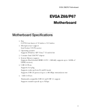
... for 3-way SLI. - 2-way SLI Bridge Bridges two (2) graphics cards together which allows for 2-way SLI. SATA III/6G Data Cables Used to support the SATAIII/6G high speed protocol and each one connects a single drive to the back panels of the chassis. - 2-Port USB 3.0 Bracket (FTW Model Only) Allows Addition of the case. SATA II/3G Data Cables Used to support the SATA protocol and each one connects a single drive to the motherboard header. - I/O Shield Fan (Optional) Exhausts Air...
... for 3-way SLI. - 2-way SLI Bridge Bridges two (2) graphics cards together which allows for 2-way SLI. SATA III/6G Data Cables Used to support the SATAIII/6G high speed protocol and each one connects a single drive to the back panels of the chassis. - 2-Port USB 3.0 Bracket (FTW Model Only) Allows Addition of the case. SATA II/3G Data Cables Used to support the SATA protocol and each one connects a single drive to the motherboard header. - I/O Shield Fan (Optional) Exhausts Air...
User Guide
Page 11
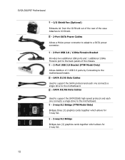
EVGA Z68/P67 Motherboard - Installation CD Contains drivers and soare needed to setup the motherboard. - ECP Panel (Optional) Allows monitoring of post codes and remote control of PCIe slot disable, voltages and CMOS reset all on one bay mounted panel. - EVGauge (Optional) Analog Gauge that represents your EVGA Motherboard. User Manual Contains Information needed to properly install and configure your CPU frequency in real time. -
EVGA Z68/P67 Motherboard - Installation CD Contains drivers and soare needed to setup the motherboard. - ECP Panel (Optional) Allows monitoring of post codes and remote control of PCIe slot disable, voltages and CMOS reset all on one bay mounted panel. - EVGauge (Optional) Analog Gauge that represents your EVGA Motherboard. User Manual Contains Information needed to properly install and configure your CPU frequency in real time. -
User Guide
Page 17
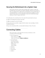
... minimum of a short circuit. This section takes you remove that do not align with a mounting hole on the motherboard. This will include: Power Connections 24-pin ATX power (PW1) 8-pin ATX 12V power (PW12-1 & PW12-2) Internal Headers Front Panel Header IEEE 1394a Header USB Headers Audio Header SATA II SATA III Chassis Fans USB 2.0 Align the mounting holes with the stand offs. 3. EVGA Z68/P67 Motherboard Most system cases have a base with...
... minimum of a short circuit. This section takes you remove that do not align with a mounting hole on the motherboard. This will include: Power Connections 24-pin ATX power (PW1) 8-pin ATX 12V power (PW12-1 & PW12-2) Internal Headers Front Panel Header IEEE 1394a Header USB Headers Audio Header SATA II SATA III Chassis Fans USB 2.0 Align the mounting holes with the stand offs. 3. EVGA Z68/P67 Motherboard Most system cases have a base with...
User Guide
Page 18
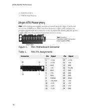
EVGA Z68/P67 Motherboard Expansion slots CMOS Clear Button PW1 is secure. Firmly plug the power supply cable into the connector and make sure it is the main power supply connector located along the edge of the board next to PW1 Board edge Figure 1. PW1 connector Plug power cable from system power supply to the DIMM slots. PW1 Pin Assignments Connector 24 12 Pin Signal 1 +3.3V 13 2 +3.3V 3 GND 4 +5V 5 GND 6 +5V 1 7 GND 8 PWROK 9 +5V_AUX 10 +12V...
EVGA Z68/P67 Motherboard Expansion slots CMOS Clear Button PW1 is secure. Firmly plug the power supply cable into the connector and make sure it is the main power supply connector located along the edge of the board next to PW1 Board edge Figure 1. PW1 connector Plug power cable from system power supply to the DIMM slots. PW1 Pin Assignments Connector 24 12 Pin Signal 1 +3.3V 13 2 +3.3V 3 GND 4 +5V 5 GND 6 +5V 1 7 GND 8 PWROK 9 +5V_AUX 10 +12V...

User Guide
Page 19
.... Align the pins to the right of the PC speaker on the mainboard allows for usage of three completely different bios versions or saving of the mainboard. EVGA Z68/P67 Motherboard PW12-1 & PW12-2, the 8-pin ATX 12V power connection, is powered on. The addition of 3 physical BIOS chips on the lower edge of profiles to the CPU. The BIOS Select Switch is located directly to the connector and press firmly...
.... Align the pins to the right of the PC speaker on the mainboard allows for usage of three completely different bios versions or saving of the mainboard. EVGA Z68/P67 Motherboard PW12-1 & PW12-2, the 8-pin ATX 12V power connection, is powered on. The addition of 3 physical BIOS chips on the lower edge of profiles to the CPU. The BIOS Select Switch is located directly to the connector and press firmly...
User Guide
Page 20
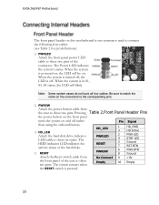
... hard disk drive indicator LED cable to these two pins. Be sure to match the name on this motherboard is powered on, the LED will blink. When the system is one connector used to connect the following four cables. (see Table 2 for pin definitions): PWRLED Attach the front panel power LED cable to these two pins of the case to these two pins. Pressing Table 2.Front Panel Header Pins the power button on the front panel turns...
... hard disk drive indicator LED cable to these two pins. Be sure to match the name on this motherboard is powered on, the LED will blink. When the system is one connector used to connect the following four cables. (see Table 2 for pin definitions): PWRLED Attach the front panel power LED cable to these two pins of the case to these two pins. Pressing Table 2.Front Panel Header Pins the power button on the front panel turns...

User Guide
Page 26
...-digit POST codes to show why the system may be failing to boot. This LED will also display current CPU socket temperatures after the system has fully booted into the Operating System. This Debug LED will remain on as long as the motherboard is on . STANDBY LED (Blue): When the System is in Standby Mode: This LED is receiving constant power. It is useful during troubleshooting situations. POWER LED...
...-digit POST codes to show why the system may be failing to boot. This LED will also display current CPU socket temperatures after the system has fully booted into the Operating System. This Debug LED will remain on as long as the motherboard is on . STANDBY LED (Blue): When the System is in Standby Mode: This LED is receiving constant power. It is useful during troubleshooting situations. POWER LED...

User Guide
Page 27
..., install the drivers and utilities listed on the CD to My Computer and click on the install screen. If the CD does not run, go to open. The CD that is shipped in the kit. 2. The kit comes with the EVGA Z68/P67 Motherboard contains the following software and drivers: Chipset Drivers Audio Drivers RAID Drivers LAN Drivers Matrix Storage USB 3.0 Drivers EVGA E-LEET User's Manual...
..., install the drivers and utilities listed on the CD to My Computer and click on the install screen. If the CD does not run, go to open. The CD that is shipped in the kit. 2. The kit comes with the EVGA Z68/P67 Motherboard contains the following software and drivers: Chipset Drivers Audio Drivers RAID Drivers LAN Drivers Matrix Storage USB 3.0 Drivers EVGA E-LEET User's Manual...
User Guide
Page 28
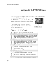
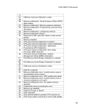
...- AMI POST Code 01 Power on the Debug LED readout located directly onboard the motherboard. Pre-memory South Bridge initialization is started Debug LED with CPU Temperature Monitor Table 6. Pre-memory CPU initialization is started 14 15- EVGA Z68/P67 Motherboard This section provides the AMI POST Codes (Table 6) for future AMI SEC error codes 0D 0E Microcode not found 0F Microcode not loaded 10 PEI Core is started 11- The POST Codes are displayed on . Reset type detection (soft/hard...
...- AMI POST Code 01 Power on the Debug LED readout located directly onboard the motherboard. Pre-memory South Bridge initialization is started Debug LED with CPU Temperature Monitor Table 6. Pre-memory CPU initialization is started 14 15- EVGA Z68/P67 Motherboard This section provides the AMI POST Codes (Table 6) for future AMI SEC error codes 0D 0E Microcode not found 0F Microcode not loaded 10 PEI Core is started 11- The POST Codes are displayed on . Reset type detection (soft/hard...
User Guide
Page 29
... IPL is started 50 Memory initialization error. No usable memory detected 54 Unspecified memory initialization error. 55 Memory not installed 56 Invalid CPU type or Speed 57 CPU mismatch 58 CPU self test failed or possible CPU cache error 59 CPU micro-code is started 33 CPU post-memory initialization. Post-Memory North Bridge initialization is not found or micro-code update SPD reading has failed 52 Memory initialization error. EVGA Z68/P67 Motherboard 1C 1D- Configuring memory 2F Memory initialization (other...
... IPL is started 50 Memory initialization error. No usable memory detected 54 Unspecified memory initialization error. 55 Memory not installed 56 Invalid CPU type or Speed 57 CPU mismatch 58 CPU self test failed or possible CPU cache error 59 CPU micro-code is started 33 CPU post-memory initialization. Post-Memory North Bridge initialization is not found or micro-code update SPD reading has failed 52 Memory initialization error. EVGA Z68/P67 Motherboard 1C 1D- Configuring memory 2F Memory initialization (other...

User Guide
Page 30
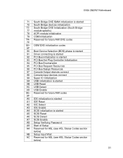
... future AMI progress codes F7 F8 Recovery PPI is not available F9 Recovery capsule is loaded F5- Reserved for future AMI progress codes E7 E8- S3 Resume Failed EB EC- EVGA Z68/P67 Motherboard is failed 5A Internal CPU error 5B reset PPI is started 61 NVRAM initialization 62 Installation of the South Bridge Runtime Services 63- CPU DXE initialization is started 67 68 PCI host bridge...
... future AMI progress codes F7 F8 Recovery PPI is not available F9 Recovery capsule is loaded F5- Reserved for future AMI progress codes E7 E8- S3 Resume Failed EB EC- EVGA Z68/P67 Motherboard is failed 5A Internal CPU error 5B reset PPI is started 61 NVRAM initialization 62 Installation of the South Bridge Runtime Services 63- CPU DXE initialization is started 67 68 PCI host bridge...
User Guide
Page 31
... IDE initialization is started A1 IDE Reset A2 IDE Detect A3 IDE Enable A4 SCSI initialization is started 9B USB Reset 9C USB Detect 9D USB Enable 9E- South Bridge DXE Initialization (South Bridge 77 module specific) 78 ACPI module initialization 79 CSM initialization 7A- OEM DXE initialization codes 8F 90 Boot Device Selection (BDS) phase is started 91 Driver connecting is started 92 PCI Bus initialization is started 93 PCI Bus Hot Plug Controller Initialization 94 PCI Bus Enumeration 95 PCI Bus...
... IDE initialization is started A1 IDE Reset A2 IDE Detect A3 IDE Enable A4 SCSI initialization is started 9B USB Reset 9C USB Detect 9D USB Enable 9E- South Bridge DXE Initialization (South Bridge 77 module specific) 78 ACPI module initialization 79 CSM initialization 7A- OEM DXE initialization codes 8F 90 Boot Device Selection (BDS) phase is started 91 Driver connecting is started 92 PCI Bus initialization is started 93 PCI Bus Hot Plug Controller Initialization 94 PCI Bus Enumeration 95 PCI Bus...

User Guide
Page 32
EVGA Z68/P67 Motherboard AD Ready To Boot event AE Legacy Boot event AF Exit Boot Services event B0 Runtime Set Virtual Address MAP Begin B1 Runtime Set Virtual Address MAP End B2 Legacy Option ROM Initialization B3 System Reset B4 USB hot plug B5 PCI bus hot plug B6 Clean-up of NVRAM B7 Configuration Reset (reset of Resources D5 No Space for future AMI codes BF C0- Out of NVRAM settings) B8- OEM BDS...
EVGA Z68/P67 Motherboard AD Ready To Boot event AE Legacy Boot event AF Exit Boot Services event B0 Runtime Set Virtual Address MAP Begin B1 Runtime Set Virtual Address MAP End B2 Legacy Option ROM Initialization B3 System Reset B4 USB hot plug B5 PCI bus hot plug B6 Clean-up of NVRAM B7 Configuration Reset (reset of Resources D5 No Space for future AMI codes BF C0- Out of NVRAM settings) B8- OEM BDS...

User Guide
Page 34
... Command Queuing NIC - Hard Disk Drive HDMI - Local Area Network LCD - Liquid Crystal Display LGA - Media Access Control MCP - Network Interface Card NTFS - Front Side Bus - Hyper-Threading HSF - Integrated memory controller IRQ - New Technology File System High Dynamic Range Lighting HPET - Input/Output IDE - Liquid Nitrogen Cooling MAC - Megahertz MMIO - EVGA Z68/P67 Motherboard FSB - For The Win! GHz - High-Definition Multimedia Interface HDR - Heat Sink Fan I /O NB - Integrated Graphics Processors IMC - Interrupt Request...
... Command Queuing NIC - Hard Disk Drive HDMI - Local Area Network LCD - Liquid Crystal Display LGA - Media Access Control MCP - Network Interface Card NTFS - Front Side Bus - Hyper-Threading HSF - Integrated memory controller IRQ - New Technology File System High Dynamic Range Lighting HPET - Input/Output IDE - Liquid Nitrogen Cooling MAC - Megahertz MMIO - EVGA Z68/P67 Motherboard FSB - For The Win! GHz - High-Definition Multimedia Interface HDR - Heat Sink Fan I /O NB - Integrated Graphics Processors IMC - Interrupt Request...

User Guide
Page 35
... System Interface SFR - V-core Voltage Drop VGA - OEM - Peripheral Component Interconnect PCIe - Peripheral Component Interconnect Extended POST - Serial Advanced Technology Attachment SB - Southbridge SCSI - Sony/Philips Digital Interconnect Format SPP - Transmission Control Protocol/Internet Protocol USB - Printed Circuit Board PCI - System Platform Processors SSD - Power on Self Test PWM - Video Graphics Array EVGA Z68/P67 Motherboard Red Green Blue SATA - Serial Presence Detect SPDIF - Quick Path Interconnect RAID - Scalable Link Interface SPD...
... System Interface SFR - V-core Voltage Drop VGA - OEM - Peripheral Component Interconnect PCIe - Peripheral Component Interconnect Extended POST - Serial Advanced Technology Attachment SB - Southbridge SCSI - Sony/Philips Digital Interconnect Format SPP - Transmission Control Protocol/Internet Protocol USB - Printed Circuit Board PCI - System Platform Processors SSD - Power on Self Test PWM - Video Graphics Array EVGA Z68/P67 Motherboard Red Green Blue SATA - Serial Presence Detect SPDIF - Quick Path Interconnect RAID - Scalable Link Interface SPD...
User Guide
Page 36
... the original purchase price of the materials (or replacement of others. Operation is connected. This equipment has been tested and found to , or used in which case the user may cause undesired operation. This equipment generates, uses and can be trademarks or service marks of the materials at EVGA Corporation's option). However, there is encouraged to try to take...
... the original purchase price of the materials (or replacement of others. Operation is connected. This equipment has been tested and found to , or used in which case the user may cause undesired operation. This equipment generates, uses and can be trademarks or service marks of the materials at EVGA Corporation's option). However, there is encouraged to try to take...


