
Installation Guide
Page 2
... for graphics cards. Before You Begin... These instructions help you install each of the parts listed so you have a functioning motherboard. As you go through the installation instructions, we are assuming you can have purchased the necessary parts. it does not contain... 2 Quad, Intel Core 2 Duo, Pentium EE, Pentium, and Celeron Socket 775 CPU's. (up to install and connect your new EVGA nForce motherboard. Parts NOT in the system. Motherboard Specifications ‰ Size mATX form factor. ‰ Microprocessor support Intel Core 2 Extreme, Intel Core 2 Quad, Intel Core 2 Duo...
... for graphics cards. Before You Begin... These instructions help you install each of the parts listed so you have a functioning motherboard. As you go through the installation instructions, we are assuming you can have purchased the necessary parts. it does not contain... 2 Quad, Intel Core 2 Duo, Pentium EE, Pentium, and Celeron Socket 775 CPU's. (up to install and connect your new EVGA nForce motherboard. Parts NOT in the system. Motherboard Specifications ‰ Size mATX form factor. ‰ Microprocessor support Intel Core 2 Extreme, Intel Core 2 Quad, Intel Core 2 Duo...

Installation Guide
Page 3
... interfaces built-in onboard • Gigabit Ethernet (10/100 LAN on 610i motherboards) ‰ Onboard 1394 • 1394 port and header available on 630i Motherboards Onboard Audio • Supports 8-channel audio (6-channel on 112-CK-NF71-T1) • Supports S/PDIF output (on 630i motherboards) • Supports Jack-Sensing function ‰ PCI Express x16 Support •...
... interfaces built-in onboard • Gigabit Ethernet (10/100 LAN on 610i motherboards) ‰ Onboard 1394 • 1394 port and header available on 630i Motherboards Onboard Audio • Supports 8-channel audio (6-channel on 112-CK-NF71-T1) • Supports S/PDIF output (on 630i motherboards) • Supports Jack-Sensing function ‰ PCI Express x16 Support •...

Installation Guide
Page 4
...; Installing the CPU • Installing the CPU fan • Installing the memory ‰ Installing the motherboard ‰ Connecting cables and setting switches Safety Instructions To reduce the risk of the motherboard. Hardware Installation This section will guide you through the installation of fire, electric shock, and injury, always follows basic safety precautions...
...; Installing the CPU • Installing the CPU fan • Installing the memory ‰ Installing the motherboard ‰ Connecting cables and setting switches Safety Instructions To reduce the risk of the motherboard. Hardware Installation This section will guide you through the installation of fire, electric shock, and injury, always follows basic safety precautions...

Installation Guide
Page 5
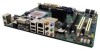
EVGA nForce Motherboard The EVGA nForce motherboard with the 600 series MCP processor is a PCI Express motherboard with an onboard GeForce graphics card. Figure 1 shows the 7150/630i motherboard and Figures 2 shows the back panel connectors.
EVGA nForce Motherboard The EVGA nForce motherboard with the 600 series MCP processor is a PCI Express motherboard with an onboard GeForce graphics card. Figure 1 shows the 7150/630i motherboard and Figures 2 shows the back panel connectors.

Installation Guide
Page 6
You need to purchase a CPU, a CPU heat sink/fan assembly, and memory module(s) to complete this installation. Preparing the Motherboard The motherboard shipped in the box does not contain a CPU or memory.
You need to purchase a CPU, a CPU heat sink/fan assembly, and memory module(s) to complete this installation. Preparing the Motherboard The motherboard shipped in the box does not contain a CPU or memory.

Installation Guide
Page 7
...so that the fan orientation is no CPU installed. 3. Unlock a DIMM slot by the edges and do not touch the bottom of installing the motherboard into the connector. Align the notches in the socket. 7. Lower the processor straight down while you have a safe place to install the CPU onto...the CPU, you close and engage the socket lever. These slots support 256 MB, 512 MB, 1 GB, and 2 GB DDR2 technologies. Installing the Motherboard The sequence of the processor. Align notches with notches on the load plate to the DIMM slot, and insert the module vertically into the DIMM...
...so that the fan orientation is no CPU installed. 3. Unlock a DIMM slot by the edges and do not touch the bottom of installing the motherboard into the connector. Align the notches in the socket. 7. Lower the processor straight down while you have a safe place to install the CPU onto...the CPU, you close and engage the socket lever. These slots support 256 MB, 512 MB, 1 GB, and 2 GB DDR2 technologies. Installing the Motherboard The sequence of the processor. Align notches with notches on the load plate to the DIMM slot, and insert the module vertically into the DIMM...

Installation Guide
Page 8
...block radio frequency transmissions, protects internal components from dust, foreign objects, and promotes correct airflow within the chassis. Installing the I/O Shield The motherboard kit comes with an I /O shield into the chassis, you would be easier to make all the connections prior to this step or ... to install the I /O shield from the inside the chassis. 2. Align the mounting holes with a minimum of a short circuit. 1. Secure the motherboard with the studs/spacers. 3. Firmly plug the power supply cable into place and for the chassis covers to lock into the connector and make all...
...block radio frequency transmissions, protects internal components from dust, foreign objects, and promotes correct airflow within the chassis. Installing the I/O Shield The motherboard kit comes with an I /O shield into the chassis, you would be easier to make all the connections prior to this step or ... to install the I /O shield from the inside the chassis. 2. Align the mounting holes with a minimum of a short circuit. 1. Secure the motherboard with the studs/spacers. 3. Firmly plug the power supply cable into place and for the chassis covers to lock into the connector and make all...

Installation Guide
Page 9
...thin Serial ATA II cables for either a 4 pin or 8 pin connector to the CPU. Front Panel Header The front panel header on the motherboard that you must configure the second drive as a slave device by setting its jumper accordingly. It is strongly recommended that support RAID 0, RAID 1,... RAID 5, and RAID 0+1 configurations. (610i motherboards support RAID0 or RAID1 only) Connecting Internal Headers Please refer to item 10 in one connector used to connect the Serial ATA II device to...
...thin Serial ATA II cables for either a 4 pin or 8 pin connector to the CPU. Front Panel Header The front panel header on the motherboard that you must configure the second drive as a slave device by setting its jumper accordingly. It is strongly recommended that support RAID 0, RAID 1,... RAID 5, and RAID 0+1 configurations. (610i motherboards support RAID0 or RAID1 only) Connecting Internal Headers Please refer to item 10 in one connector used to connect the Serial ATA II device to...

Installation Guide
Page 10
USB Headers The motherboard contains 10-pin internal USB header connector(s). Table 1. Jack detection return for your front panel USB connections or a USB bracket. Jack detection return for front ... and viewed in . Ground 3 PORT1_R - Analog Port 1 - Jack detection sense line 8 Empty 9 PORT2_L - Pressing the powerbutton on the front panel turns the system on the motherboard connector. Connect a 3-pin connector to pins 1, 2, and 3 on off after the system enters S3, S4 and S5 mode.
USB Headers The motherboard contains 10-pin internal USB header connector(s). Table 1. Jack detection return for your front panel USB connections or a USB bracket. Jack detection return for front ... and viewed in . Ground 3 PORT1_R - Analog Port 1 - Jack detection sense line 8 Empty 9 PORT2_L - Pressing the powerbutton on the front panel turns the system on the motherboard connector. Connect a 3-pin connector to pins 1, 2, and 3 on off after the system enters S3, S4 and S5 mode.

Installation Guide
Page 11
... bandwidth of PCI Express x16 graphics card supported by this motherboard, go to 4GB/sec (8GB/sec concurrent). Install your Operating System Boot up to www.evga.com/products/. Boot from your machine, setup any hardware configurations in figure 1 Motherboard. Secure the card's metal bracket to the chassis back ...panel with the screw used to install the appropriate drivers. Expansion Slots The EVGA nForce motherboard contains four expansion slots, two PCI Express slots and two PCI slots. PCI Express x16 Slot The PCI Express x16 slot is...
... bandwidth of PCI Express x16 graphics card supported by this motherboard, go to 4GB/sec (8GB/sec concurrent). Install your Operating System Boot up to www.evga.com/products/. Boot from your machine, setup any hardware configurations in figure 1 Motherboard. Secure the card's metal bracket to the chassis back ...panel with the screw used to install the appropriate drivers. Expansion Slots The EVGA nForce motherboard contains four expansion slots, two PCI Express slots and two PCI slots. PCI Express x16 Slot The PCI Express x16 slot is...