
Installation Guide
Page 2
... Extreme, Intel Core 2 Quad, Intel Core 2 Duo, Pentium EE, Pentium, and Celeron. (610i supports up to 1066MHz FSB CPU's) ‰ Operating systems Supports Windows XP and Windows Vista. ‰ Contains NVIDIA nForce MCP and integrated GeForce graphics ‰ System...microprocessor: Intel Core 2 Extreme, Intel Core 2 Quad, Intel Core 2 Duo, Pentium EE, Pentium, and Celeron Socket 775 CPU's. (up to 1066Mhz FSB on 610i motherboards) ‰ Cooling fan and heat sink for the microprocessor ‰ System memory ...all the hardware necessary to install and connect your new EVGA nForce motherboard.
... Extreme, Intel Core 2 Quad, Intel Core 2 Duo, Pentium EE, Pentium, and Celeron. (610i supports up to 1066MHz FSB CPU's) ‰ Operating systems Supports Windows XP and Windows Vista. ‰ Contains NVIDIA nForce MCP and integrated GeForce graphics ‰ System...microprocessor: Intel Core 2 Extreme, Intel Core 2 Quad, Intel Core 2 Duo, Pentium EE, Pentium, and Celeron Socket 775 CPU's. (up to 1066Mhz FSB on 610i motherboards) ‰ Cooling fan and heat sink for the microprocessor ‰ System memory ...all the hardware necessary to install and connect your new EVGA nForce motherboard.

Installation Guide
Page 4
... removing or installing any equipment from/to the computer chassis. The topics covered in this section are: ‰ Preparing the motherboard • Installing the CPU • Installing the CPU fan • Installing the memory ‰ Installing the motherboard ‰ Connecting cables and setting switches Safety Instructions To reduce the risk of the...
... removing or installing any equipment from/to the computer chassis. The topics covered in this section are: ‰ Preparing the motherboard • Installing the CPU • Installing the CPU fan • Installing the memory ‰ Installing the motherboard ‰ Connecting cables and setting switches Safety Instructions To reduce the risk of the...

Installation Guide
Page 6
You need to purchase a CPU, a CPU heat sink/fan assembly, and memory module(s) to complete this installation. Preparing the Motherboard The motherboard shipped in the box does not contain a CPU or memory.
You need to purchase a CPU, a CPU heat sink/fan assembly, and memory module(s) to complete this installation. Preparing the Motherboard The motherboard shipped in the box does not contain a CPU or memory.

Installation Guide
Page 7
... tilting or sliding it into the DIMM slot. Follow the instruction that came with notches on the chassis you have a safe place to install the CPU onto the motherboard. 1. Be sure that can be at both sides of the processor. These slots support 256 MB, 512 MB, 1 GB, and 2 ...a DIMM slot by pushing down while you close and engage the socket lever. Align notches with your fan assembly. Close the load plate over the CPU and press down and away from the load plate. 4. Remove the protective socket cover from the socket. 2. Installing Memory DIMMs Your new motherboard has...
... tilting or sliding it into the DIMM slot. Follow the instruction that came with notches on the chassis you have a safe place to install the CPU onto the motherboard. 1. Be sure that can be at both sides of the processor. These slots support 256 MB, 512 MB, 1 GB, and 2 ...a DIMM slot by pushing down while you close and engage the socket lever. Align notches with your fan assembly. Close the load plate over the CPU and press down and away from the load plate. 4. Remove the protective socket cover from the socket. 2. Installing Memory DIMMs Your new motherboard has...

Installation Guide
Page 8
... recommended that you would be easier to make all the connections prior to this step or to secure the motherboard and then make sure the CPU Fan assembly is aligned with the studs/spacers. 3. Determine if it would need to obtain the proper size from the chassis supplier. Securing the Motherboard... from dust, foreign objects, and promotes correct airflow within the chassis. Ensure that is aligned with a minimum of the chassis. Note: Be sure that the CPU fan assembly has enough clearance for the expansion cards.
... recommended that you would be easier to make all the connections prior to this step or to secure the motherboard and then make sure the CPU Fan assembly is aligned with the studs/spacers. 3. Determine if it would need to obtain the proper size from the chassis supplier. Securing the Motherboard... from dust, foreign objects, and promotes correct airflow within the chassis. Ensure that is aligned with a minimum of the chassis. Note: Be sure that the CPU fan assembly has enough clearance for the expansion cards.

Installation Guide
Page 9
... drives, you use an 8-pin ATX 12V power supply; Connecting Serial ATA Cables The Serial ATA II connector is used to provide power to the CPU. Align the pins to the motherboard. Connecting IDE Hard Disk Drives The IDE connector supports Ultra ATA 133/100/66 IDE hard disk drives. The...
... drives, you use an 8-pin ATX 12V power supply; Connecting Serial ATA Cables The Serial ATA II connector is used to provide power to the CPU. Align the pins to the motherboard. Connecting IDE Hard Disk Drives The IDE connector supports Ultra ATA 133/100/66 IDE hard disk drives. The...

Installation Guide
Page 10
... is present 5 PORT2_R - Most cases come with a 10 pin standard block which will need to the header. Ground 3 PORT1_R - Active signal that the CPU fan cable can be individual plugs which will be either a 3-pin or a 4-pin connector. Note that indicates FP audio is pressed. USB Headers The motherboard... be plugged in the PC Health Status section of the case to these two pins. Analog Port 1 - Jack detection sense line 8 Empty 9 PORT2_L - CPU Fan Connector 4 3 21 GND SENSE PWR CONTROL Both fans are two types fan connections, the system fan and the...
... is present 5 PORT2_R - Most cases come with a 10 pin standard block which will need to the header. Ground 3 PORT1_R - Active signal that the CPU fan cable can be individual plugs which will be either a 3-pin or a 4-pin connector. Note that indicates FP audio is pressed. USB Headers The motherboard... be plugged in the PC Health Status section of the case to these two pins. Analog Port 1 - Jack detection sense line 8 Empty 9 PORT2_L - CPU Fan Connector 4 3 21 GND SENSE PWR CONTROL Both fans are two types fan connections, the system fan and the...

Installation Guide
Page 12
... ROM,BIOS and message EEPROM Check Flash type and copy flash Write/erase routines Test and Reset CMOS Load Chipset Defaults Initialize onboard clock generator CPU ID and initialize L1/L2 cache Initialize first 120 interrupt vectors Vector Table with SPURIOUS_INT_HDLR and initialize INT 00h-1Fh according to INT_TBL Test CMOS...
... ROM,BIOS and message EEPROM Check Flash type and copy flash Write/erase routines Test and Reset CMOS Load Chipset Defaults Initialize onboard clock generator CPU ID and initialize L1/L2 cache Initialize first 120 interrupt vectors Vector Table with SPURIOUS_INT_HDLR and initialize INT 00h-1Fh according to INT_TBL Test CMOS...
Installation Guide
Page 13
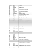
...40 41 42 43 44 Name Reserved Re-initial KB Reserved HPM init Reserved Program chipset Init PNP Shadow VBIOS Clock Setup BDA Reserved CPU Speed detect Reserved Init video Reserved Video memory test Reserved Reserved Reserved Reserved Reserved Early keyboard reset Reserved Test DMA Controller 0 Reserved ...of chipset registers Init PNP Shadow system/video BIOS Gen Init onboard clock generator and sensor Setup BIOS DATA AREA (BDA) Chipset programming and CPU Speed detect Initialize Video Test Video Memory and display Logos Early Keyboard Reset Test DMA channel 0 Test DMA channel 1 Test DMA Page ...
...40 41 42 43 44 Name Reserved Re-initial KB Reserved HPM init Reserved Program chipset Init PNP Shadow VBIOS Clock Setup BDA Reserved CPU Speed detect Reserved Init video Reserved Video memory test Reserved Reserved Reserved Reserved Reserved Early keyboard reset Reserved Test DMA Controller 0 Reserved ...of chipset registers Init PNP Shadow system/video BIOS Gen Init onboard clock generator and sensor Setup BIOS DATA AREA (BDA) Chipset programming and CPU Speed detect Initialize Video Test Video Memory and display Logos Early Keyboard Reset Test DMA channel 0 Test DMA channel 1 Test DMA Page ...

Installation Guide
Page 14
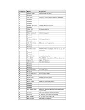
... 640K and extended memory above 1MB using Virtual 8086 mode, page mode and clear the memory Detect CPU speed and display CPU vendor specific version string and turn on all necessary CPU features Display PnP logo and PnP early init Setup virus protect according to PS2 Mouse port ACPI sub... Reserved 4C Reserved 4D Reserved 4E Init APIC 4F Reserved 50 USB init Initialize 51 Reserved 52 Memory Test 53 Reserved 54 Reserved 55 CPU display 56 Reserved 57 PnP Init 58 Reserved 59 Setup Virus 5A Reserved 5B Awdflash Load 5C Reserved 5D Onboard I/O Init 5E Reserved...
... 640K and extended memory above 1MB using Virtual 8086 mode, page mode and clear the memory Detect CPU speed and display CPU vendor specific version string and turn on all necessary CPU features Display PnP logo and PnP early init Setup virus protect according to PS2 Mouse port ACPI sub... Reserved 4C Reserved 4D Reserved 4E Init APIC 4F Reserved 50 USB init Initialize 51 Reserved 52 Memory Test 53 Reserved 54 Reserved 55 CPU display 56 Reserved 57 PnP Init 58 Reserved 59 Setup Virus 5A Reserved 5B Awdflash Load 5C Reserved 5D Onboard I/O Init 5E Reserved...
Installation Guide
Page 15
Read/Write CPU registers Write all CMOS values back to Setup Set low stack Boot via INT 19h. Code(hex) 6D 6E 6F 70 71 72 73 74 ... 8E Reserved 8F IRQ12 Enable 90 Reserved 91 Reserved 92 Reserved 93 Boot Medium Read 94 Final Init 95 NumLock 96 Boot Attempt C0 Base CPU test Description Initialize floppy disk drive Install FDD and setup BIOS data area parameters Initialize hard drive controller IDE device detection Initialize serial ports Initialize...
Read/Write CPU registers Write all CMOS values back to Setup Set low stack Boot via INT 19h. Code(hex) 6D 6E 6F 70 71 72 73 74 ... 8E Reserved 8F IRQ12 Enable 90 Reserved 91 Reserved 92 Reserved 93 Boot Medium Read 94 Final Init 95 NumLock 96 Boot Attempt C0 Base CPU test Description Initialize floppy disk drive Install FDD and setup BIOS data area parameters Initialize hard drive controller IDE device detection Initialize serial ports Initialize...