User Guide
Page 1
...137; Power Supply ‰ Graphics Card EVGA assumes you have purchased all the hardware necessary to 480Mbps transmission rate Motherboard Specifications ‰ Size mATX form factor. ‰ Microprocessor support Intel Core 2 Extreme, Intel Core 2 Quad, Intel Core 2 Duo, Pentium EE, Pentium, and Celeron. (The e-7050/610i supports up to 1066MHz FSB CPU's) ...137; USB 2.0 Ports • Supports hot plug • Up to eight (4 onboard) USB 2.0 ports • Supports USB 2.0 protocol up to install and connect your new EVGA e-7050/610i GPU motherboard with integrated GeForce graphics processing.
...137; Power Supply ‰ Graphics Card EVGA assumes you have purchased all the hardware necessary to 480Mbps transmission rate Motherboard Specifications ‰ Size mATX form factor. ‰ Microprocessor support Intel Core 2 Extreme, Intel Core 2 Quad, Intel Core 2 Duo, Pentium EE, Pentium, and Celeron. (The e-7050/610i supports up to 1066MHz FSB CPU's) ...137; USB 2.0 Ports • Supports hot plug • Up to eight (4 onboard) USB 2.0 ports • Supports USB 2.0 protocol up to install and connect your new EVGA e-7050/610i GPU motherboard with integrated GeForce graphics processing.
User Guide
Page 3
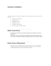
...; Connecting cables and setting switches Safety Instructions To reduce the risk of the motherboard. Figure 1 shows the 7150/630i motherboard and Figures 2 shows the back panel connectors. EVGA nForce Motherboard The EVGA nForce motherboard with the 600 series MCP processor is a PCI Express motherboard with an onboard GeForce graphics card. Remember to remove power from your computer...
...; Connecting cables and setting switches Safety Instructions To reduce the risk of the motherboard. Figure 1 shows the 7150/630i motherboard and Figures 2 shows the back panel connectors. EVGA nForce Motherboard The EVGA nForce motherboard with the 600 series MCP processor is a PCI Express motherboard with an onboard GeForce graphics card. Remember to remove power from your computer...
User Guide
Page 4
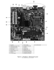
...CPU Fan Connector 4. FDD Connector 6. 24-Pin ATX Power Connector 7. Front Panel Audio Header 12. IDE HDD Connector 8. PCI-E x16 Slot 15. Motherboard CMOS Battery 5 19. USB 2.0 Header 11. Clear CMOS Jumper Figure 1. Back Panel Connectors 16. 4-Pin CPU Power Connector 17. 3-Pin System... Fan Connector 18. PCI-E x1 Slot 14. e-7010/610i Motherboard Layout Note: Actual motherboard may vary from pictures Front Panel Header 6 7 10. 15 12 12 13 14 17 11 10 18 19 10 16 1 2 3 4...
...CPU Fan Connector 4. FDD Connector 6. 24-Pin ATX Power Connector 7. Front Panel Audio Header 12. IDE HDD Connector 8. PCI-E x16 Slot 15. Motherboard CMOS Battery 5 19. USB 2.0 Header 11. Clear CMOS Jumper Figure 1. Back Panel Connectors 16. 4-Pin CPU Power Connector 17. 3-Pin System... Fan Connector 18. PCI-E x1 Slot 14. e-7010/610i Motherboard Layout Note: Actual motherboard may vary from pictures Front Panel Header 6 7 10. 15 12 12 13 14 17 11 10 18 19 10 16 1 2 3 4...
User Guide
Page 6
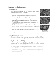
...are many different heat sink types that came with notches on the socket. 6. The plastic clips at least one memory module. 1. Preparing the Motherboard Installing the CPU Be very careful when handling the CPU. Align the notches in the socket. 7. Align notches with your fan assembly. Installing System... Memory (DIMMs) Your new motherboard has two 1.8V 240-pin slots for your chassis type and your fan assembly. Unlock a DIMM slot by the edges. Close the load ...
...are many different heat sink types that came with notches on the socket. 6. The plastic clips at least one memory module. 1. Preparing the Motherboard Installing the CPU Be very careful when handling the CPU. Align the notches in the socket. 7. Align notches with your fan assembly. Installing System... Memory (DIMMs) Your new motherboard has two 1.8V 240-pin slots for your chassis type and your fan assembly. Unlock a DIMM slot by the edges. Close the load ...
User Guide
Page 7
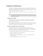
... supplier. If the I/O shield does not fit into the chassis, you remove that stud to prevent the possibility of a short circuit. 1. Carefully place the motherboard onto the studs/spacers located inside of the chassis. Note: Be sure that the CPU fan assembly has enough clearance for the expansion cards. Press... the chassis depends on the chassis you are using and if you are studs that do not align with the vents on the motherboard, it is recommended that you would be secured to the chassis and help to prevent short circuits. Installing the I /O shield into place and make ...
... supplier. If the I/O shield does not fit into the chassis, you remove that stud to prevent the possibility of a short circuit. 1. Carefully place the motherboard onto the studs/spacers located inside of the chassis. Note: Be sure that the CPU fan assembly has enough clearance for the expansion cards. Press... the chassis depends on the chassis you are using and if you are studs that do not align with the vents on the motherboard, it is recommended that you would be secured to the chassis and help to prevent short circuits. Installing the I /O shield into place and make ...
User Guide
Page 8
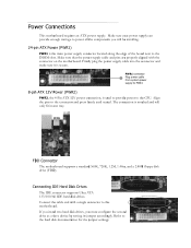
... properly aligned with a single connector to the connector and press firmly until seated. Align the pins to the motherboard. Connect the cable end with the connector on the motherboard. Refer to the CPU. Firmly plug the power supply cable into the connector and make sure it is used... as a slave device by setting its jumper accordingly. If you install two hard disk drives, you will only fit in one way. FDD Connector The motherboard supports a standard 360K, 720K, 1.2M, 1.44m, and a 2.88M floppy disk drive (FDD). PWR1 connector Plug power cable from system power supply to...
... properly aligned with a single connector to the connector and press firmly until seated. Align the pins to the motherboard. Connect the cable end with the connector on the motherboard. Refer to the CPU. Firmly plug the power supply cable into the connector and make sure it is used... as a slave device by setting its jumper accordingly. If you install two hard disk drives, you will only fit in one way. FDD Connector The motherboard supports a standard 360K, 720K, 1.2M, 1.44m, and a 2.88M floppy disk drive (FDD). PWR1 connector Plug power cable from system power supply to...
User Guide
Page 9
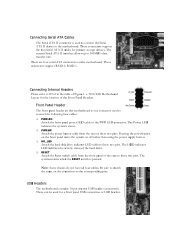
...Panel Headers. Be sure to match the name on this motherboard is one connector used to connect the Serial ATA II device to the motherboard. Front Panel Header The front panel header on the connectors to these two pins. e-7010/610i Motherboard Layout for a front panel USB connection or USB bracket... current Serial ATA II interface allows up to these two pins. Note: Some chassis do not have all four cables. USB Headers The motherboard contains 10-pin internal USB header connector(s). The Power LED indicates the system's status. ‰ PWRSW Attach the power button cable from the...
...Panel Headers. Be sure to match the name on this motherboard is one connector used to connect the Serial ATA II device to the motherboard. Front Panel Header The front panel header on the connectors to these two pins. e-7010/610i Motherboard Layout for a front panel USB connection or USB bracket... current Serial ATA II interface allows up to these two pins. Note: Some chassis do not have all four cables. USB Headers The motherboard contains 10-pin internal USB header connector(s). The Power LED indicates the system's status. ‰ PWRSW Attach the power button cable from the...
User Guide
Page 10
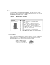
... indicates FP audio is present 5 PORT2_R - Ground 3 PORT1_R - right channel (Headphone) 6 SENSE1_RETURN - In some cases there will be plugged in to pins 1, 2, and 3 on the motherboard connector. Active signal that the CPU fan cable can be either a 3-pin or a 4-pin connector. Analog port 2 - The fan speed can be detected and viewed...
... indicates FP audio is present 5 PORT2_R - Ground 3 PORT1_R - right channel (Headphone) 6 SENSE1_RETURN - In some cases there will be plugged in to pins 1, 2, and 3 on the motherboard connector. Active signal that the CPU fan cable can be either a 3-pin or a 4-pin connector. Analog port 2 - The fan speed can be detected and viewed...
User Guide
Page 11
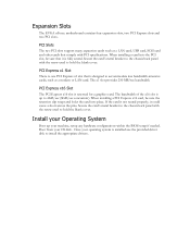
... PCI Express x1 slot that it could cause a short across the pins. Once your operating system is reserved for a graphics card. Expansion Slots The EVGA nForce motherboard contains four expansion slots, two PCI Express slots and two PCI slots. Secure the card's metal bracket to install the appropriate drivers. PCI Express x16...
... PCI Express x1 slot that it could cause a short across the pins. Once your operating system is reserved for a graphics card. Expansion Slots The EVGA nForce motherboard contains four expansion slots, two PCI Express slots and two PCI slots. Secure the card's metal bracket to install the appropriate drivers. PCI Express x16...