User Guide
Page 1
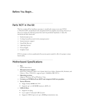
... Pentium, and Celeron. (The e-7050/610i supports up to 1066MHz FSB CPU's) ‰ Operating systems Supports Windows XP and Windows Vista. ‰ Contains an NVIDIA nForce MCP and integrated GeForce graphics ‰ System Memory • Single-channel DDR2 667/533 • Supports up to 4 GB DDR2 memory...microprocessor ‰ System memory support ‰ Hard Disk Drive(s) ‰ Operating System ‰ Power Supply ‰ Graphics Card EVGA assumes you have purchased all the hardware necessary to install and connect your new EVGA e-7050/610i GPU motherboard with integrated GeForce graphics ...
... Pentium, and Celeron. (The e-7050/610i supports up to 1066MHz FSB CPU's) ‰ Operating systems Supports Windows XP and Windows Vista. ‰ Contains an NVIDIA nForce MCP and integrated GeForce graphics ‰ System Memory • Single-channel DDR2 667/533 • Supports up to 4 GB DDR2 memory...microprocessor ‰ System memory support ‰ Hard Disk Drive(s) ‰ Operating System ‰ Power Supply ‰ Graphics Card EVGA assumes you have purchased all the hardware necessary to install and connect your new EVGA e-7050/610i GPU motherboard with integrated GeForce graphics ...
User Guide
Page 6
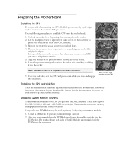
... The plastic clips at least one memory bank populated to store it. 5. Preparing the Motherboard Installing the CPU Be very careful when handling the CPU. Lift the load plate. Close the load plate over the CPU and press down while you have a safe place to ensure normal operation. *Any of... socket when there is fully seated and level in the processor with this motherboard. Remove the processor from its protective cover, making sure you hold it into the socket Note: Make sure the CPU is no CPU installed. 3. These slots support 256 MB, 512 MB, 1 GB, and 2 GB DDR2 technologies. ...
... The plastic clips at least one memory bank populated to store it. 5. Preparing the Motherboard Installing the CPU Be very careful when handling the CPU. Lift the load plate. Close the load plate over the CPU and press down while you have a safe place to ensure normal operation. *Any of... socket when there is fully seated and level in the processor with this motherboard. Remove the processor from its protective cover, making sure you hold it into the socket Note: Make sure the CPU is no CPU installed. 3. These slots support 256 MB, 512 MB, 1 GB, and 2 GB DDR2 technologies. ...
User Guide
Page 8
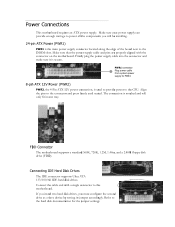
...provide power to the hard disk documentation for the jumper settings. FDD Connector The motherboard supports a standard 360K, 720K, 1.2M, 1.44m, and a 2.88M floppy disk drive (FDD). Connecting IDE Hard Disk Drives The IDE connector supports Ultra ATA 133/100/66 IDE hard disk drives. Connect the cable end with...the connector on the motherboard. The connection is notched and will be installing. 24-pin ATX Power (PWR1) PWR1 is the main power supply connector located along the edge of the board next to the connector and press firmly until seated. Refer to the CPU. If you install ...
...provide power to the hard disk documentation for the jumper settings. FDD Connector The motherboard supports a standard 360K, 720K, 1.2M, 1.44m, and a 2.88M floppy disk drive (FDD). Connecting IDE Hard Disk Drives The IDE connector supports Ultra ATA 133/100/66 IDE hard disk drives. Connect the cable end with...the connector on the motherboard. The connection is notched and will be installing. 24-pin ATX Power (PWR1) PWR1 is the main power supply connector located along the edge of the board next to the connector and press firmly until seated. Refer to the CPU. If you install ...
User Guide
Page 10
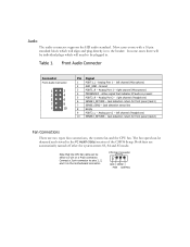
...can be plugged in. Analog Port 1 - Audio The audio connector supports the HD audio standard. Analog Port 1 - left channel (Headphone) 10 SENSE2_RETURN - right channel (Headphone) 6 SENSE1_RETURN - left channel (Microphone) 2 AUD_GND - CPU Fan Connector 4 3 21 GND SENSE PWR CONTROL Most cases come ...types fan connections, the system fan and the CPU fan. In some cases there will be detected and viewed in to pins 1, 2, and 3 on the motherboard connector. right channel (Microphone) 4 PRESENCE# - Active signal that the CPU fan cable can be individual plugs which will...
...can be plugged in. Analog Port 1 - Audio The audio connector supports the HD audio standard. Analog Port 1 - left channel (Headphone) 10 SENSE2_RETURN - right channel (Headphone) 6 SENSE1_RETURN - left channel (Microphone) 2 AUD_GND - CPU Fan Connector 4 3 21 GND SENSE PWR CONTROL Most cases come ...types fan connections, the system fan and the CPU fan. In some cases there will be detected and viewed in to pins 1, 2, and 3 on the motherboard connector. right channel (Microphone) 4 PRESENCE# - Active signal that the CPU fan cable can be individual plugs which will...
