Installation Guide
Page 4
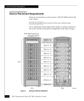
... Installation 4 EMC Departmental Switch DS-16B2 Installation Guide Rear EMC2056 Power distribution must support the number of outlets required for clarity. Device Placement Requirements Device Placement Requirements There are no restrictions on page 3. Note: Switch bezels are typically located at the top of the DS-16B2 switch in pairs. Switches are removed for the switch and the switch power rating...
... Installation 4 EMC Departmental Switch DS-16B2 Installation Guide Rear EMC2056 Power distribution must support the number of outlets required for clarity. Device Placement Requirements Device Placement Requirements There are no restrictions on page 3. Note: Switch bezels are typically located at the top of the DS-16B2 switch in pairs. Switches are removed for the switch and the switch power rating...
Installation Guide
Page 5
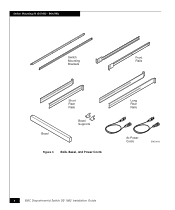
... for your PDU) DS-16B2-RKL kit only) EMC Departmental Switch DS-16B2 Installation Guide 5 see illustration on page 21. 2 per switch 2 short rail assemblies (20.5 inches to 27 inches) 2 per switch 2 long rail assemblies (27 inches to 34 inches) 2 per switch 1 U standard-profile or low-profile bezel (front rack panel) 1 per switch Bezel supports 2 per switch 2 8-foot IEC power...
... for your PDU) DS-16B2-RKL kit only) EMC Departmental Switch DS-16B2 Installation Guide 5 see illustration on page 21. 2 per switch 2 short rail assemblies (20.5 inches to 27 inches) 2 per switch 2 long rail assemblies (27 inches to 34 inches) 2 per switch 1 U standard-profile or low-profile bezel (front rack panel) 1 per switch Bezel supports 2 per switch 2 8-foot IEC power...
Installation Guide
Page 6
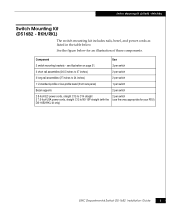
RKH/RKL) Switch Mounting Brackets Front Rails Bezel Short Rear Rails Bezel Supports Figure 3 Rails. Bezel, and Power Cords Long Rear Rails Ac Power Cords EMC2042 6 EMC Departmental Switch DS-16B2 Installation Guide Switch Mounting Kit (DS16B2 -
RKH/RKL) Switch Mounting Brackets Front Rails Bezel Short Rear Rails Bezel Supports Figure 3 Rails. Bezel, and Power Cords Long Rear Rails Ac Power Cords EMC2042 6 EMC Departmental Switch DS-16B2 Installation Guide Switch Mounting Kit (DS16B2 -
Installation Guide
Page 8
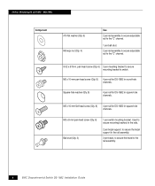
...-hole washer (Qty. 8) 4 per rail for DS-16B2 in square-hole channels. Used to secure mounting brackets to the rails. 2 per bezel support, to secure the bezel support to the rail assembly. 2 per mounting bracket to secure mounting bracket to the rail assembly. 8 EMC Departmental Switch DS-16B2 Installation Guide M5 x 10-mm pan-head screw (Qty...
...-hole washer (Qty. 8) 4 per rail for DS-16B2 in square-hole channels. Used to secure mounting brackets to the rails. 2 per bezel support, to secure the bezel support to the rail assembly. 2 per mounting bracket to secure mounting bracket to the rail assembly. 8 EMC Departmental Switch DS-16B2 Installation Guide M5 x 10-mm pan-head screw (Qty...
Installation Guide
Page 17
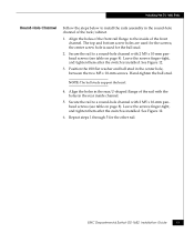
...and ball stud in the rear, U-shaped flange of the rack/cabinet. 1. EMC Departmental Switch DS-16B2 Installation Guide 17 The top and bottom screw holes are used for the ball stud. 2. Secure the rail to a round-hole channel with 2 M5 x 10-mm panhead screws (see table on page 8). Leave..., and tighten them after the switch is used for the other rail. the center screw hole is installed. Hand-tighten the ball stud. NOTE: The ball studs support the bezel. 4. Secure the rail to a round-hole channel with the holes in the round-hole channel of the rail with 2 M5...
...and ball stud in the rear, U-shaped flange of the rack/cabinet. 1. EMC Departmental Switch DS-16B2 Installation Guide 17 The top and bottom screw holes are used for the ball stud. 2. Secure the rail to a round-hole channel with 2 M5 x 10-mm panhead screws (see table on page 8). Leave..., and tighten them after the switch is used for the other rail. the center screw hole is installed. Hand-tighten the ball stud. NOTE: The ball studs support the bezel. 4. Secure the rail to a round-hole channel with the holes in the round-hole channel of the rail with 2 M5...
Installation Guide
Page 24
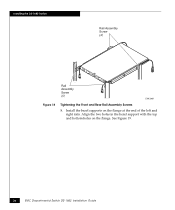
See Figure 19. 24 EMC Departmental Switch DS-16B2 Installation Guide Installing the DS-16B2 Switch Rail Assembly Screw (4) Figure 18 Rail Assembly Screw (4) EMC2051 Tightening the Front and Rear Rail Assembly Screws 8. Align the two holes in the bezel support with the top and bottom holes on the flange at the end of the left and right rails. Install the bezel supports on the flange.
See Figure 19. 24 EMC Departmental Switch DS-16B2 Installation Guide Installing the DS-16B2 Switch Rail Assembly Screw (4) Figure 18 Rail Assembly Screw (4) EMC2051 Tightening the Front and Rear Rail Assembly Screws 8. Align the two holes in the bezel support with the top and bottom holes on the flange at the end of the left and right rails. Install the bezel supports on the flange.
Installation Guide
Page 25
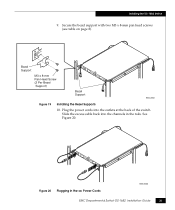
Slide the excess cable back into the outlets at the back of the switch. Secure the bezel support with two M3 x 8-mm pan head screws (see table on page 8). See Figure 20. Plug the power cords into the channels in the ac Power Cords EMC2053 EMC Departmental Switch DS-16B2 Installation Guide 25 Bezel Support M3 x 8-mm Pan Head Screw (2 Per Bezel Support) Bezel Support EMC2052 Figure 19 Installing the Bezel Supports 10. Installing the DS-16B2 Switch 9. Figure 20 Plugging in the rails.
Slide the excess cable back into the outlets at the back of the switch. Secure the bezel support with two M3 x 8-mm pan head screws (see table on page 8). See Figure 20. Plug the power cords into the channels in the ac Power Cords EMC2053 EMC Departmental Switch DS-16B2 Installation Guide 25 Bezel Support M3 x 8-mm Pan Head Screw (2 Per Bezel Support) Bezel Support EMC2052 Figure 19 Installing the Bezel Supports 10. Installing the DS-16B2 Switch 9. Figure 20 Plugging in the rails.
Installation Guide
Page 27
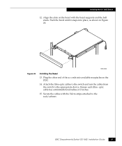
EMC Departmental Switch DS-16B2 Installation Guide 27 optic cable has a minimum bend radius of the ac cords into place, as shown in Figure 22. Ensure each fibre- Secure the cables with the bezel supports and the ball studs. Installing the DS-16B2 Switch 12. Plug the other end of 2 inches. 15. Align the slots on the PDU...
EMC Departmental Switch DS-16B2 Installation Guide 27 optic cable has a minimum bend radius of the ac cords into place, as shown in Figure 22. Ensure each fibre- Secure the cables with the bezel supports and the ball studs. Installing the DS-16B2 Switch 12. Plug the other end of 2 inches. 15. Align the slots on the PDU...