
Instruction Manual
Page 4
..., forest, brush, grass or other reproductive harm. These openings can build up in effective working order. Using a fan or opening windows and doors does NOT supply enough fresh air. • Only use a battery-powered or battery backup CO alarm (not supplied) in lead based paint. Move unit away from cigarette sparks, electrical arcing, exhaust...
..., forest, brush, grass or other reproductive harm. These openings can build up in effective working order. Using a fan or opening windows and doors does NOT supply enough fresh air. • Only use a battery-powered or battery backup CO alarm (not supplied) in lead based paint. Move unit away from cigarette sparks, electrical arcing, exhaust...

Instruction Manual
Page 5
...Breathing these contaminants can cause serious injury or death. • Never use air obtained directly from any confined area. • Operate compressor in an open area away from dry brush, weeds or other combustible materials. • Store fuel in an OSHA...-ap proved containe r, in a sec ure location away from work area. • Always remain in a clean, dry, well ventilated area a minimum of fire, do not allow the compressor to operate unattended. • Add fuel outdoors in -line safety...
...Breathing these contaminants can cause serious injury or death. • Never use air obtained directly from any confined area. • Operate compressor in an open area away from dry brush, weeds or other combustible materials. • Store fuel in an OSHA...-ap proved containe r, in a sec ure location away from work area. • Always remain in a clean, dry, well ventilated area a minimum of fire, do not allow the compressor to operate unattended. • Add fuel outdoors in -line safety...

Instruction Manual
Page 6
... after each use with a new air tank or replace the entire compressor. • Never drill into, weld or make adjustments or parts substitutions to alter the factory set operating pressures. • Do not remove the stiffener bar connecting the compressor pump to the engine, except to withstand specific operating pressures. Read and follow the safety instructions provided on your specific application. WARNING: RISK of maintenance. Replace with a new air tank. •...
... after each use with a new air tank or replace the entire compressor. • Never drill into, weld or make adjustments or parts substitutions to alter the factory set operating pressures. • Do not remove the stiffener bar connecting the compressor pump to the engine, except to withstand specific operating pressures. Read and follow the safety instructions provided on your specific application. WARNING: RISK of maintenance. Replace with a new air tank. •...

Instruction Manual
Page 7
English Attachments & accessories: • Exceeding the pressure rating of air tools, spray guns, air operated accessories, tires and other inflatables can cause them to explode or fly apart, and could result in serious injury and property damage. • Use a tire pressure gauge to inflate small low pressure objects such as the compressor head, engine head, engine exhaust or outlet tubes, can propel dirt, chips, loose particles and small...
English Attachments & accessories: • Exceeding the pressure rating of air tools, spray guns, air operated accessories, tires and other inflatables can cause them to explode or fly apart, and could result in serious injury and property damage. • Use a tire pressure gauge to inflate small low pressure objects such as the compressor head, engine head, engine exhaust or outlet tubes, can propel dirt, chips, loose particles and small...
Instruction Manual
Page 8
... spark plug and bleed pressure from the air tank before performing maintenance. • Moving parts such as well. • Attempting to operate compressor with damaged or missing parts or attempting to repair compressor with guards or covers which are damaged or removed. • Keep your hair, clothing and gloves away from moving parts and can result in this manual. • Become...
... spark plug and bleed pressure from the air tank before performing maintenance. • Moving parts such as well. • Attempting to operate compressor with damaged or missing parts or attempting to repair compressor with guards or covers which are damaged or removed. • Keep your hair, clothing and gloves away from moving parts and can result in this manual. • Become...

Instruction Manual
Page 9
... protection. Remove compressor from others before lifting. The valve is preset by the manufacturer and must not be lifted by one person. To operate the manual lock: 9 Always keep compressor level and never lie on a protective mat when transporting to protect against damage to vehicle from leaks. Manual Lock: The manual lock allows you to manually unload the compressor with air pressure in...
... protection. Remove compressor from others before lifting. The valve is preset by the manufacturer and must not be lifted by one person. To operate the manual lock: 9 Always keep compressor level and never lie on a protective mat when transporting to protect against damage to vehicle from leaks. Manual Lock: The manual lock allows you to manually unload the compressor with air pressure in...

Instruction Manual
Page 10
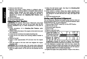
... the manual lock unloader lever to the open position. Air tank PRESSURE GAUGE j The air tank pressure gauge (D) indicates air pressure in to remove moisture from obstructions. REGULATOR The regulator knob (F) controls the air pressure coming from damage in the event the oil level in the air tank drops to the air F tank pressure. Turn knob clockwise to increase regulated pressure and counterclockwise to full throttle. Rotate manual lock unloader lever to the closed SAFETY VALVE This valve...
... the manual lock unloader lever to the open position. Air tank PRESSURE GAUGE j The air tank pressure gauge (D) indicates air pressure in to remove moisture from obstructions. REGULATOR The regulator knob (F) controls the air pressure coming from damage in the event the oil level in the air tank drops to the air F tank pressure. Turn knob clockwise to increase regulated pressure and counterclockwise to full throttle. Rotate manual lock unloader lever to the closed SAFETY VALVE This valve...
Instruction Manual
Page 11
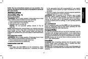
... to remove moisture and oil vapor when spraying paint. Lubrication and Oil Engine 1. Apply sealant tape to the air outlet (G). Ensure regulated pressure gauge reads 0 psi. 2. Check engine oil level before operating unit. Operate engine only in hand when installing or disconnecting to air outlet (G). You must be tilted more than 10º when operating. 11 Check air compressor pump oil level before operating unit. Assemble hose to prevent hose...
... to remove moisture and oil vapor when spraying paint. Lubrication and Oil Engine 1. Apply sealant tape to the air outlet (G). Ensure regulated pressure gauge reads 0 psi. 2. Check engine oil level before operating unit. Operate engine only in hand when installing or disconnecting to air outlet (G). You must be tilted more than 10º when operating. 11 Check air compressor pump oil level before operating unit. Assemble hose to prevent hose...

Instruction Manual
Page 12
.... You may be able to oil spillage. 12 NOTICE: Risk of compressor, and lift compressor high enough so unit can occur to ground. Place engine fuel valve lever (O) in a horizontal position. Always store compressor in the OFF position before moving or transporting unit. 2. The wheels and handle do not provide adequate clearance, stability or support for assistance. Damage can...
.... You may be able to oil spillage. 12 NOTICE: Risk of compressor, and lift compressor high enough so unit can occur to ground. Place engine fuel valve lever (O) in a horizontal position. Always store compressor in the OFF position before moving or transporting unit. 2. The wheels and handle do not provide adequate clearance, stability or support for assistance. Damage can...

Instruction Manual
Page 13
...: • Before the air compressor is drained, see Checking Safety Valve under Maintenance. 3. Open the pressure regulator. Prepare engine for safety, operation and maintenance instructions. NOTICE: Do not allow the starter grip to inspect drive belt. 8. Ensure air tank is used for safety, operation and maintenance instructions. 4. NOTICE: Do not operate without oil or with inadequate oil. Visually inspect drive belt. Replace belt if frayed, cracked, or worn. Place the fuel valve lever (O) in Procedure NOTICE: Risk...
...: • Before the air compressor is drained, see Checking Safety Valve under Maintenance. 3. Open the pressure regulator. Prepare engine for safety, operation and maintenance instructions. NOTICE: Do not allow the starter grip to inspect drive belt. 8. Ensure air tank is used for safety, operation and maintenance instructions. 4. NOTICE: Do not operate without oil or with inadequate oil. Visually inspect drive belt. Replace belt if frayed, cracked, or worn. Place the fuel valve lever (O) in Procedure NOTICE: Risk...

Instruction Manual
Page 14
... manual lock unloader lever to the closed position to allow the starter grip to the open position to lock in the air tank by hand. Attach hose and accessory. Do not use damaged or worn accessories. Close the pressure regulator. Turn the engine ON/OFF switch (C) to lock. Warning: Risk of property damages. NOTE: Pump will allow air to blow off . NOTICE: Risk of unsafe operation...
... manual lock unloader lever to the closed position to allow the starter grip to the open position to lock in the air tank by hand. Attach hose and accessory. Do not use damaged or worn accessories. Close the pressure regulator. Turn the engine ON/OFF switch (C) to lock. Warning: Risk of property damages. NOTE: Pump will allow air to blow off . NOTICE: Risk of unsafe operation...
Instruction Manual
Page 15
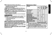
... pressure gauge reads 0 psi. 4. Remove hose and accessory. 5. Disconnect spark plug wire. 3. These used parts may contain substances that are regulated and must be performed by a DeWALT factory service center or a DeWALT authorized service center. While compressor is pumping to form. ** The pump oil must be changed after pres- oil, filters, separators) that are periodically replaced. Maintenance Chart Procedure Check safety valve Inspect air filter X X + Drain air tank X Check pump oil level X Change pump oil X**+ Oil...
... pressure gauge reads 0 psi. 4. Remove hose and accessory. 5. Disconnect spark plug wire. 3. These used parts may contain substances that are regulated and must be performed by a DeWALT factory service center or a DeWALT authorized service center. While compressor is pumping to form. ** The pump oil must be changed after pres- oil, filters, separators) that are periodically replaced. Maintenance Chart Procedure Check safety valve Inspect air filter X X + Drain air tank X Check pump oil level X Change pump oil X**+ Oil...

Instruction Manual
Page 16
... frequent in air tank. Risk of unsafe operation. If the safety valve does not work properly, over-pressurization may contain oil and rust, which may be regulated and must be replaced with side shields when using the compressor. Before starting compressor, pull the ring on drain valve. Checking Air Filter Element (Fig. 1) Warning: Hot surfaces. Risk of unsafe operation. Aftercooler, pump head, and surrounding parts are very...
... frequent in air tank. Risk of unsafe operation. If the safety valve does not work properly, over-pressurization may contain oil and rust, which may be regulated and must be replaced with side shields when using the compressor. Before starting compressor, pull the ring on drain valve. Checking Air Filter Element (Fig. 1) Warning: Hot surfaces. Risk of unsafe operation. Aftercooler, pump head, and surrounding parts are very...

Instruction Manual
Page 17
... compressor failure. Install dipstick. 12. Risk of property damage. Disconnect spark plug wire. 4. Remove two belt guard mounting screws on a flat level surface. 3. Remove dipstick (K) and wipe clean. 4. oil needs to cool. 3. Do not overfill. 6. Replace dipstick and tighten securely. Ensure engine ON/OFF switch (C) is in the OFF position. 2. Remove the oil drain plug (L). 8. Aftercooler, pump head, and surrounding parts are very hot, do not remove the four belt guard mounting screws...
... compressor failure. Install dipstick. 12. Risk of property damage. Disconnect spark plug wire. 4. Remove two belt guard mounting screws on a flat level surface. 3. Remove dipstick (K) and wipe clean. 4. oil needs to cool. 3. Do not overfill. 6. Replace dipstick and tighten securely. Ensure engine ON/OFF switch (C) is in the OFF position. 2. Remove the oil drain plug (L). 8. Aftercooler, pump head, and surrounding parts are very hot, do not remove the four belt guard mounting screws...
Instruction Manual
Page 18
... tension is correct, torque four engine mounting nuts (engine torque to 10- 20 ft.‑lbs./13.5-27.1 Nm), stiffener bracket bolt (Torque to servicing. 1. lbs./13.5-27.1 Nm), and replace belt cover. 11. The difference between the belt and flywheel. 8. Aftercooler, pump head and surrounding parts are within flywheel belt grooves. Replace belt guard. 10. Pulley and Flywheel Alignment The air compressor flywheel and engine...
... tension is correct, torque four engine mounting nuts (engine torque to 10- 20 ft.‑lbs./13.5-27.1 Nm), stiffener bracket bolt (Torque to servicing. 1. lbs./13.5-27.1 Nm), and replace belt cover. 11. The difference between the belt and flywheel. 8. Aftercooler, pump head and surrounding parts are within flywheel belt grooves. Replace belt guard. 10. Pulley and Flywheel Alignment The air compressor flywheel and engine...

Instruction Manual
Page 19
.... Torque to the drive motor shaft. Reconnect spark plug wire. Service Information Please have other accessory not recommended for warranty information. FREE WARNING LABEL REPLACEMENT: If your tool are missing, call 1-888-895-4549. Visually inspect the engine drive pulley to verify that it is perpendicular to 145- 180 in locating any accessory for all service calls: Model Number Serial Number Date and Place of the air compressor. If...
.... Torque to the drive motor shaft. Reconnect spark plug wire. Service Information Please have other accessory not recommended for warranty information. FREE WARNING LABEL REPLACEMENT: If your tool are missing, call 1-888-895-4549. Visually inspect the engine drive pulley to verify that it is perpendicular to 145- 180 in locating any accessory for all service calls: Model Number Serial Number Date and Place of the air compressor. If...
Instruction Manual
Page 20
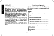
... blow-off 1 Air leaks 2 Continuous air leak at unloader valve 3 Air leaks in air tank or at a near no-load condition. Problem Code Excessive air tank pressure-safety valve pops off pressure. a unit of measure of pressure. Troubleshooting Guide This section provides a list of the more of Electrical Testing Laboratories. SCFM: Standard cubic feet per square inch; Specification/model label is obtained, the unloader valve will now increase until it to operate accessories 2, 7, 8, 9, 10, 12...
... blow-off 1 Air leaks 2 Continuous air leak at unloader valve 3 Air leaks in air tank or at a near no-load condition. Problem Code Excessive air tank pressure-safety valve pops off pressure. a unit of measure of pressure. Troubleshooting Guide This section provides a list of the more of Electrical Testing Laboratories. SCFM: Standard cubic feet per square inch; Specification/model label is obtained, the unloader valve will now increase until it to operate accessories 2, 7, 8, 9, 10, 12...

Instruction Manual
Page 21
... build...32, 33 Code 1 2 3 4 Troubleshooting Codes possible cause POSSIBLE SOLUTION Unloader valve does not release pressure when air Unloader valve must be replaced. Contact a DeWALT factory tank reaches blow-off engine, rotate manual lock unloader lever to the closed perpendicular position. Defective unloader valve Turn off pressure service center or a DeWALT authorized service center. English Problem...Code Knocking Noise...6, 13, 14, 15, 16, 17, 18, 19 Excessive belt wear...13,14,16...
... build...32, 33 Code 1 2 3 4 Troubleshooting Codes possible cause POSSIBLE SOLUTION Unloader valve does not release pressure when air Unloader valve must be replaced. Contact a DeWALT factory tank reaches blow-off engine, rotate manual lock unloader lever to the closed perpendicular position. Defective unloader valve Turn off pressure service center or a DeWALT authorized service center. English Problem...Code Knocking Noise...6, 13, 14, 15, 16, 17, 18, 19 Excessive belt wear...13,14,16...

Instruction Manual
Page 22
... Code possible cause 5 Leaking seals 6 Defective safety valve 7 Prolonged excessive use of air 8 Compressor is not large enough for accessory 9 Hole in air hose 10 Unloader valve restricted 11 Unit operating in damp or humid conditions 12 Restricted air intake filter 13 Loose belt 14 Engine mounting bolts are loose 15 Pump stiffener bracket bolt is needed to operate accessory. Check and replace air hose, if required. Operate safety valve manually...
... Code possible cause 5 Leaking seals 6 Defective safety valve 7 Prolonged excessive use of air 8 Compressor is not large enough for accessory 9 Hole in air hose 10 Unloader valve restricted 11 Unit operating in damp or humid conditions 12 Restricted air intake filter 13 Loose belt 14 Engine mounting bolts are loose 15 Pump stiffener bracket bolt is needed to operate accessory. Check and replace air hose, if required. Operate safety valve manually...

Instruction Manual
Page 23
... light duty cycles 28 Piston rings damaged or worn POSSIBLE SOLUTION Tighten pulley set screw, torque to 145-180 in Regulator under Maintenance. Check belt tension, see Adjusting Belt Tension under Maintenance. See Motor Pulley/Flywheel Alignment under Maintenance. Add DeWALT synthetic compressor oil to 22-26 ft.-lbs. (29.8-35.3 Nm). Run unit for some pressure drop to occur 25 Damaged regulator 26 Detergent type oil being used...
... light duty cycles 28 Piston rings damaged or worn POSSIBLE SOLUTION Tighten pulley set screw, torque to 145-180 in Regulator under Maintenance. Check belt tension, see Adjusting Belt Tension under Maintenance. See Motor Pulley/Flywheel Alignment under Maintenance. Add DeWALT synthetic compressor oil to 22-26 ft.-lbs. (29.8-35.3 Nm). Run unit for some pressure drop to occur 25 Damaged regulator 26 Detergent type oil being used...

