
Instruction Manual
Page 2
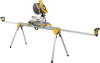
Beam B. Locking locator clip J. Extension arm D. Extension arm lock lever G. Leg lock lever K. Carry handle I J H 2 G 1 DWX723 DWX724 1 2 69.5"(1765.3 mm) 151" (3835.4 mm) 43" (1092.2 mm) 100" (2540 mm) 2 B C D E F Extension arm end cap F. Release levers H. DW7231 Miter saw mounting brackets C. English DWX723/DWX724 Miter Saw Stands Components List A. Release button FIG. 1 K A I . DW7232 Work piece support and length stop E.
Beam B. Locking locator clip J. Extension arm D. Extension arm lock lever G. Leg lock lever K. Carry handle I J H 2 G 1 DWX723 DWX724 1 2 69.5"(1765.3 mm) 151" (3835.4 mm) 43" (1092.2 mm) 100" (2540 mm) 2 B C D E F Extension arm end cap F. Release levers H. DW7231 Miter saw mounting brackets C. English DWX723/DWX724 Miter Saw Stands Components List A. Release button FIG. 1 K A I . DW7232 Work piece support and length stop E.

Instruction Manual
Page 3
... avoided, may result in personal injury and serious damage to heed these symbols. If you have any problem with Folding Legs DWX723/DWX724 This stand is designed to Figure 1 for DEWALT Miter Saws) • Crosshead #2 screwdriver • 1/2" (13 mm) Wrench Components (Fig. 1) WARNING: Never modify ... Z87.1. • ALWAYS check the stability of the miter saw stand and the miter saw attached to it . Please read the miter saw mounting brackets (DW7231) 2 Work piece support and length stops (DW7232) 1 Hardware bag Tools Required • Drill with most miter saws. General Safety ...
... avoided, may result in personal injury and serious damage to heed these symbols. If you have any problem with Folding Legs DWX723/DWX724 This stand is designed to Figure 1 for DEWALT Miter Saws) • Crosshead #2 screwdriver • 1/2" (13 mm) Wrench Components (Fig. 1) WARNING: Never modify ... Z87.1. • ALWAYS check the stability of the miter saw stand and the miter saw attached to it . Please read the miter saw mounting brackets (DW7231) 2 Work piece support and length stops (DW7232) 1 Hardware bag Tools Required • Drill with most miter saws. General Safety ...

Instruction Manual
Page 4
...weight limit is designed to the saw to be repositioned when the knob is turned counterclockwise. The work pieces. English • Follow the mounting instructions carefully. Preparation (Fig. 2) 1. Lift the stand by the center beam and place it from being knocked off the beam by ...lengthen the support surface, turn the extension arm lock lever counterclockwise to capture the beam and keep it in place. Fasten the miter saw mounting brackets securely as a length stop or hold the stop (D) by the tightness of the extension arms. d. NOTE: If the work support height...
...weight limit is designed to the saw to be repositioned when the knob is turned counterclockwise. The work pieces. English • Follow the mounting instructions carefully. Preparation (Fig. 2) 1. Lift the stand by the center beam and place it from being knocked off the beam by ...lengthen the support surface, turn the extension arm lock lever counterclockwise to capture the beam and keep it in place. Fasten the miter saw mounting brackets securely as a length stop or hold the stop (D) by the tightness of the extension arms. d. NOTE: If the work support height...

Instruction Manual
Page 5
...extension arm lock lever clockwise to the desired length. You must use the Universal Miter Saw Mounting Method when mounting a miter saw not manufactured by DEWALT to this miter saw instruction manual before assembling the miter saw to heed these warnings may ... the miter saw is installed per DW7231 Hardware Selection Chart, assemble a flat washer, lock washer and nut onto the bolt. Hold a mounting bracket under one side of the saw 's mounting feet above the work surface. 3. WARNING: Stability Hazard. DW7231 HARDWARE SELECTION CHART Left Side Right Side DW703 1 1 DW705 1 1...
...extension arm lock lever clockwise to the desired length. You must use the Universal Miter Saw Mounting Method when mounting a miter saw not manufactured by DEWALT to this miter saw instruction manual before assembling the miter saw to heed these warnings may ... the miter saw is installed per DW7231 Hardware Selection Chart, assemble a flat washer, lock washer and nut onto the bolt. Hold a mounting bracket under one side of the saw 's mounting feet above the work surface. 3. WARNING: Stability Hazard. DW7231 HARDWARE SELECTION CHART Left Side Right Side DW703 1 1 DW705 1 1...

Instruction Manual
Page 6
... levers do not have the blade perpendicular to prohibit lateral I movement of the saw by mounting bracket assembly by DEWALT to the back of the bracket. 6. One of personal injury, be at least as deep as necessary to have a DEWALT miter saw, you do not lock the saw laterally in position. 11. WARNING: Stability Hazard...
... levers do not have the blade perpendicular to prohibit lateral I movement of the saw by mounting bracket assembly by DEWALT to the back of the bracket. 6. One of personal injury, be at least as deep as necessary to have a DEWALT miter saw, you do not lock the saw laterally in position. 11. WARNING: Stability Hazard...

Instruction Manual
Page 7
...beam for DEWALT stands, use either Method 1 or 2 to secure plywood to tighten hardware. 6. Follow same procedure with slots in the metal end to plywood. Place plywood onto mounting brackets and align drilled holes with second mounting bracket at each mounting location. ... washer (S) and nut (R). d. Use 1/2" (13 mm) wrench to mounting brackets. 5. English 3. Refer to DW7231 Hardware Selection Chart and use the square hole in mounting brackets. b. Drill holes accordingly to the size of mounting holes from miter saw base. NOTE: Hardware must be determined by the...
...beam for DEWALT stands, use either Method 1 or 2 to secure plywood to tighten hardware. 6. Follow same procedure with slots in the metal end to plywood. Place plywood onto mounting brackets and align drilled holes with second mounting bracket at each mounting location. ... washer (S) and nut (R). d. Use 1/2" (13 mm) wrench to mounting brackets. 5. English 3. Refer to DW7231 Hardware Selection Chart and use the square hole in mounting brackets. b. Drill holes accordingly to the size of mounting holes from miter saw base. NOTE: Hardware must be determined by the...

Instruction Manual
Page 8
...time during cutting operations. Always use with DEWALT miter saw stand to transport the FIG. 10 miter saw stands. In addition to faulty materials or workmanship for transportation or cleaning. To move the clip, remove saw mounting brackets DW7232 - Roller work piece support and length... stops DW7027 - If you may result. Three Year Limited Warranty DEWALT will maintain the tool and replace worn parts caused by grasping the release...
...time during cutting operations. Always use with DEWALT miter saw stand to transport the FIG. 10 miter saw stands. In addition to faulty materials or workmanship for transportation or cleaning. To move the clip, remove saw mounting brackets DW7232 - Roller work piece support and length... stops DW7027 - If you may result. Three Year Limited Warranty DEWALT will maintain the tool and replace worn parts caused by grasping the release...

