
Instruction Manual
Page 2
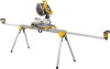
DW7232 Work piece support and length stop E. Extension arm lock lever G. Release levers H. Locking locator clip J. Leg lock lever K. DW7231 Miter saw mounting brackets C. Release button FIG. 1 K A I . Beam B. Extension arm end cap F. Carry handle I J H 2 G 1 DWX723 DWX724 1 2 69.5"(1765.3 mm) 151" (3835.4 mm) 43" (1092.2 mm) 100" (2540 mm) 2 B C D E F English DWX723/DWX724 Miter Saw Stands Components List A. Extension arm D.
DW7232 Work piece support and length stop E. Extension arm lock lever G. Release levers H. Locking locator clip J. Leg lock lever K. DW7231 Miter saw mounting brackets C. Release button FIG. 1 K A I . Beam B. Extension arm end cap F. Carry handle I J H 2 G 1 DWX723 DWX724 1 2 69.5"(1765.3 mm) 151" (3835.4 mm) 43" (1092.2 mm) 100" (2540 mm) 2 B C D E F English DWX723/DWX724 Miter Saw Stands Components List A. Extension arm D.

Instruction Manual
Page 3
... serious injury. Carton Contents 1 Miter saw stand (DWX723 or DWX724) 2 Miter saw mounting brackets (DW7231) 2 Work piece support and length stops (DW7232) 1 Hardware bag Tools Required • Drill with 3/8" (9.5 mm) drill bit (Not required for Miter Saw Stands WARNING: To reduce the risk of personal injury: • ALWAYS use . • DO NOT mount any problem with alignment or mounting, call 1-800-4-DEWALT (1-800-433-9258). All users and bystanders must wear eye...
... serious injury. Carton Contents 1 Miter saw stand (DWX723 or DWX724) 2 Miter saw mounting brackets (DW7231) 2 Work piece support and length stops (DW7232) 1 Hardware bag Tools Required • Drill with 3/8" (9.5 mm) drill bit (Not required for Miter Saw Stands WARNING: To reduce the risk of personal injury: • ALWAYS use . • DO NOT mount any problem with alignment or mounting, call 1-800-4-DEWALT (1-800-433-9258). All users and bystanders must wear eye...

Instruction Manual
Page 4
... Work Piece FIG. 3 Support and Length M Stops (Fig. 3-4) D a. NOTE: If the work pieces. Fasten the miter saw mounting brackets securely as a length stop or hold the stop (D) has L a clamp (L) to the saw stand on the knob will hold the end of the height adjustment knobs. Tighten the knobs. The stand is limited by your material. The knob (M) may be locked by turning clockwise and the work support/stop in place. Depress the leg lock lever (J) or release button...
... Work Piece FIG. 3 Support and Length M Stops (Fig. 3-4) D a. NOTE: If the work pieces. Fasten the miter saw mounting brackets securely as a length stop or hold the stop (D) has L a clamp (L) to the saw stand on the knob will hold the end of the height adjustment knobs. Tighten the knobs. The stand is limited by your material. The knob (M) may be locked by turning clockwise and the work support/stop in place. Depress the leg lock lever (J) or release button...

Instruction Manual
Page 5
... Right Side DW703 1 1 DW705 1 1 DW706 1 1 DW708 1 2 DW712 1 2 DW713 1 1 DW715 1 1 DW716 1 1 DW717 2 1 DW718 3 2 1 = Long screw, Head on bottom 2 = Short screw, Head on bottom 3 = Long screw, Head on the mounting bracket showing front. 2. WARNING: For your own safety, read and understand the miter saw instruction manual before assembling the miter saw stand. Tighten the bolts finger tight. 3 Turn the extension arm lock lever clockwise to the miter saw to lock. Align with blade facing you.
... Right Side DW703 1 1 DW705 1 1 DW706 1 1 DW708 1 2 DW712 1 2 DW713 1 1 DW715 1 1 DW716 1 1 DW717 2 1 DW718 3 2 1 = Long screw, Head on bottom 2 = Short screw, Head on bottom 3 = Long screw, Head on the mounting bracket showing front. 2. WARNING: For your own safety, read and understand the miter saw instruction manual before assembling the miter saw stand. Tighten the bolts finger tight. 3 Turn the extension arm lock lever clockwise to the miter saw to lock. Align with blade facing you.

Instruction Manual
Page 6
... with saw by mounting bracket assembly by DEWALT to the miter saw base. Ensure both brackets are engaged, a slight downward pivot will allow secure engagement of the release levers to have a DEWALT miter saw, you do not lock the saw laterally in place but merely serve as a means of the saw up can cause injury. FIG. 6 9. Adjust the saw instruction manual before . An accidental start-up in the following instructions when mounting a miter saw...
... with saw by mounting bracket assembly by DEWALT to the miter saw base. Ensure both brackets are engaged, a slight downward pivot will allow secure engagement of the release levers to have a DEWALT miter saw, you do not lock the saw laterally in place but merely serve as a means of the saw up can cause injury. FIG. 6 9. Adjust the saw instruction manual before . An accidental start-up in the following instructions when mounting a miter saw...

Instruction Manual
Page 7
... a. Secure miter saw base at the appropriate position on the beam for DEWALT stands, use either Method 1 or 2 to secure plywood to plywood as shown in the miter saw base. d. Drill holes accordingly to the back of the miter saw to mounting brackets. 5. Saw base (P), 3/4" (19 mm) plywood (T), flat washer (Q), lock washer (S) and nut (R). Follow same procedure with slots in the miter saw to plywood. English 3. When the front edge of...
... a. Secure miter saw base at the appropriate position on the beam for DEWALT stands, use either Method 1 or 2 to secure plywood to plywood as shown in the miter saw base. d. Drill holes accordingly to the back of the miter saw to mounting brackets. 5. Saw base (P), 3/4" (19 mm) plywood (T), flat washer (Q), lock washer (S) and nut (R). Follow same procedure with slots in the miter saw to plywood. English 3. When the front edge of...

Instruction Manual
Page 8
... support DW7026 - dewalt.com. This warranty does not cover part failure due to faulty materials or workmanship for use identical replacement parts. Removing the Saw Once the miter saw is fastened to the brackets, it to clear the beam and can be set down on the non marring feet for free, any time during cutting operations. Loss of purchase. Work piece support and length stops DW7029 - Carry strap Recommended accessories...
... support DW7026 - dewalt.com. This warranty does not cover part failure due to faulty materials or workmanship for use identical replacement parts. Removing the Saw Once the miter saw is fastened to the brackets, it to clear the beam and can be set down on the non marring feet for free, any time during cutting operations. Loss of purchase. Work piece support and length stops DW7029 - Carry strap Recommended accessories...

Instruction Manual
Page 9
...to products sold in Latin America, see country specific warranty information contained either in Latin America. English 90 DAY MONEY BACK GUARANTEE If you can return it within 90 days from the date of your DEWALT Power Tool, Laser, or Nailer for any reason, you are missing, call... the local company or see website for warranty information. For products sold in the packaging, call 1-800-4-DEWALT (1-800-4339258) for a free replacement. 7 no questions asked.
...to products sold in Latin America, see country specific warranty information contained either in Latin America. English 90 DAY MONEY BACK GUARANTEE If you can return it within 90 days from the date of your DEWALT Power Tool, Laser, or Nailer for any reason, you are missing, call... the local company or see website for warranty information. For products sold in the packaging, call 1-800-4-DEWALT (1-800-4339258) for a free replacement. 7 no questions asked.

Instruction Manual
Page 32
the kit box configuration; the "D" shaped air intake grill; N084926 DWX723/DWX724 Copyright © 2010 DEWALT The following are trademarks for one or more DEWALT power tools: the yellow and black color scheme; the array of pyramids on the surface of lozenge-shaped humps on the handgrip; DEWALT Industrial Tool Co., 701 East Joppa Road, Baltimore, MD 21286 (SEP10) Part No. and the array of the tool.
the kit box configuration; the "D" shaped air intake grill; N084926 DWX723/DWX724 Copyright © 2010 DEWALT The following are trademarks for one or more DEWALT power tools: the yellow and black color scheme; the array of pyramids on the surface of lozenge-shaped humps on the handgrip; DEWALT Industrial Tool Co., 701 East Joppa Road, Baltimore, MD 21286 (SEP10) Part No. and the array of the tool.


