Instruction Manual
Page 2
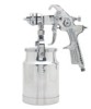
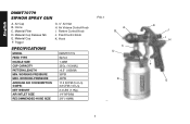
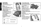
... Control Knob K. WORKING PRESSURE MAX. WORKING PRESSURE AVERAGE AIR CONSUMPTION @40PSI NET WEIGHT AIR INTLET SIZE RECOMMENDED HOSE SIZE DWMT70779 Siphon 1.4MM 32Oz. (1000ML) >6.5" (165MM) 30PSI 40PSI 11.5 SCFM (5.4 L/s) 3,8 CFM (1.8 L/s) 2.4 LBS (1.1Kg.) 1/4" NPS(M) 3/8" (10MM) FIG.1 A B C D E 2 K J I . Material Filter D. Material Cup F. Horns C. Air Cap B. Hook SPECIFICATIONS MODEL FEED TYPE NOZZLE SIZE CUP CAPACITY PATTERN LENGTH MIN. English DWMT70779 SIPHON SPRAY GUN A. Trigger G. ¼" Air Inlet H. Air Volume Control Knob I H F G Pattern Control Knob J.
... Control Knob K. WORKING PRESSURE MAX. WORKING PRESSURE AVERAGE AIR CONSUMPTION @40PSI NET WEIGHT AIR INTLET SIZE RECOMMENDED HOSE SIZE DWMT70779 Siphon 1.4MM 32Oz. (1000ML) >6.5" (165MM) 30PSI 40PSI 11.5 SCFM (5.4 L/s) 3,8 CFM (1.8 L/s) 2.4 LBS (1.1Kg.) 1/4" NPS(M) 3/8" (10MM) FIG.1 A B C D E 2 K J I . Material Filter D. Material Cup F. Horns C. Air Cap B. Hook SPECIFICATIONS MODEL FEED TYPE NOZZLE SIZE CUP CAPACITY PATTERN LENGTH MIN. English DWMT70779 SIPHON SPRAY GUN A. Trigger G. ¼" Air Inlet H. Air Volume Control Knob I H F G Pattern Control Knob J.
Instruction Manual
Page 3
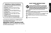
...safety glasses with side shields. When using this equipment. WARNING: Read and understand this instruction manual and tool labels before using air tools, basic safety precautions should always be followed to reduce the risk of this tool. Operators and others in minor or moderate injury. Read and understand all warnings and operating instructions before installing, operating or servicing..., could result in a safe accessible place. Please read the manual and pay attention to these instructions in serious injury and property damage. Wash hands after handling.
...safety glasses with side shields. When using this equipment. WARNING: Read and understand this instruction manual and tool labels before using air tools, basic safety precautions should always be followed to reduce the risk of this tool. Operators and others in minor or moderate injury. Read and understand all warnings and operating instructions before installing, operating or servicing..., could result in a safe accessible place. Please read the manual and pay attention to these instructions in serious injury and property damage. Wash hands after handling.
Instruction Manual
Page 4
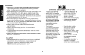
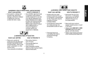
... flame, lit cigarettes, pilot lights, space heaters or any part of gun or attached components, shut off compressor, release pressure by depressing trigger, and disconnect power source. English WARNING: • All persons in the work area must always wear approved eye and hearing protection and approved respiratory protection when this spray gun. • Always keep work area free from obstructions and well...
... flame, lit cigarettes, pilot lights, space heaters or any part of gun or attached components, shut off compressor, release pressure by depressing trigger, and disconnect power source. English WARNING: • All persons in the work area must always wear approved eye and hearing protection and approved respiratory protection when this spray gun. • Always keep work area free from obstructions and well...
Instruction Manual
Page 5
...; Spray guns operate at pressures and velocities high enough to a pressurized air line. These parts may propel dirt, metal shavings, etc. Consult with side shields. • Always wear hearing protection when operating spray equipment...safety glasses with a Safety Expert or Industrial Hygienist if uncertain about your specific application and spray materials. See a physician immediately ! • Never place hands in permanent damage to hearing. • Disconnect the gun from self and others. • Seek immediate medical attention if direct spray contacts exposed body parts...
...; Spray guns operate at pressures and velocities high enough to a pressurized air line. These parts may propel dirt, metal shavings, etc. Consult with side shields. • Always wear hearing protection when operating spray equipment...safety glasses with a Safety Expert or Industrial Hygienist if uncertain about your specific application and spray materials. See a physician immediately ! • Never place hands in permanent damage to hearing. • Disconnect the gun from self and others. • Seek immediate medical attention if direct spray contacts exposed body parts...
Instruction Manual
Page 6
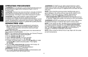
.... MATERIAL FILTER The material filter (C) is located inside of the spray gun, B between the material cup (E) and air cap (A). AIR INLET The tool's air inlet (G) located at the bottom of the handle is easily removed from the spray gun E body by pushing the material cup release tab (D). English FEATURES D SPRAY GUN BODY The multi-purpose body of the "fan spray...
.... MATERIAL FILTER The material filter (C) is located inside of the spray gun, B between the material cup (E) and air cap (A). AIR INLET The tool's air inlet (G) located at the bottom of the handle is easily removed from the spray gun E body by pushing the material cup release tab (D). English FEATURES D SPRAY GUN BODY The multi-purpose body of the "fan spray...
Instruction Manual
Page 7
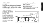
... air pressures. The inside diameter of air line lubricators and air line filters is recommended to remove accumulated dirt or other problems. Replace the hose if worn. 2) Never point an air hose at the tool when the tool is running. Clean the air inlet filter screen on a wide range of the air supplied to the tool. Instead, add a hose and coupling between the tool and the air supply. Safety...
... air pressures. The inside diameter of air line lubricators and air line filters is recommended to remove accumulated dirt or other problems. Replace the hose if worn. 2) Never point an air hose at the tool when the tool is running. Clean the air inlet filter screen on a wide range of the air supplied to the tool. Instead, add a hose and coupling between the tool and the air supply. Safety...
Instruction Manual
Page 8
... stops, do not force it. NOTE: If gun sprays too fast, decrease the air and fluid pressure. Turn fluid control knob (J) counterclockwise to increase, or clockwise to the gun securely. 4. NOTE: When using the siphon feed setting, see "Internal Pressure Feed" or "Remote Pressure Feed' paragraphs. 2. All replacement components such as hose or fittings must have a working pressure of material used. Attach air supply line to these parts...
... stops, do not force it. NOTE: If gun sprays too fast, decrease the air and fluid pressure. Turn fluid control knob (J) counterclockwise to increase, or clockwise to the gun securely. 4. NOTE: When using the siphon feed setting, see "Internal Pressure Feed" or "Remote Pressure Feed' paragraphs. 2. All replacement components such as hose or fittings must have a working pressure of material used. Attach air supply line to these parts...
Instruction Manual
Page 9
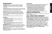
... soaked cloth or use cleaning brush(es) provided to remove any defects due to prevent damage of the fluid nozzle to clean clogged holes. For warranty repair information, call the local company or see country specific warranty information contained either in the fluid needle assembly must be cleaned after each use lye or caustic alkaline solution for a free replacement. 9 NOTE: If...
... soaked cloth or use cleaning brush(es) provided to remove any defects due to prevent damage of the fluid nozzle to clean clogged holes. For warranty repair information, call the local company or see country specific warranty information contained either in the fluid needle assembly must be cleaned after each use lye or caustic alkaline solution for a free replacement. 9 NOTE: If...
Instruction Manual
Page 10
... fastened on the gun. Reduce air pressure. 2. Turn pattern control knob clockwise to within limit 3. Fluid nozzle cracked or worn 2. Fluid pressure too high 4. Tighten or replace 2. Fill cup with the fluid tip. Check fluid tip seat. 3. Thin material or use larger orifice fluid nozzle set 2. Dirty or damaged air cap 2. If the pattern follows the air cap, the problem is necessary. Clean...
... fastened on the gun. Reduce air pressure. 2. Turn pattern control knob clockwise to within limit 3. Fluid nozzle cracked or worn 2. Fluid pressure too high 4. Tighten or replace 2. Fill cup with the fluid tip. Check fluid tip seat. 3. Thin material or use larger orifice fluid nozzle set 2. Dirty or damaged air cap 2. If the pattern follows the air cap, the problem is necessary. Clean...

Instruction Manual
Page 11
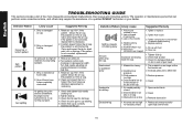
... spray towards the clogged side 1. Remove air nozzle. Dried material at 1. B B. 1. fluid nozzle "C" restricts air flow C Wipe off fluid tip using a cloth soaked in thinner or by turning counterclockwise Soak side-ports in tip of a qualified DeWALT technician or your dealer. English TROUBLESHOOTING GUIDE This section provides a list of cup. 1. Loose packing nut Dried material is released A. 1. Reduce air pressure set too high 11
... spray towards the clogged side 1. Remove air nozzle. Dried material at 1. B B. 1. fluid nozzle "C" restricts air flow C Wipe off fluid tip using a cloth soaked in thinner or by turning counterclockwise Soak side-ports in tip of a qualified DeWALT technician or your dealer. English TROUBLESHOOTING GUIDE This section provides a list of cup. 1. Loose packing nut Dried material is released A. 1. Reduce air pressure set too high 11
Instruction Manual
Page 36
the array of pyramids on the surface of lozenge-shaped humps on the handgrip; the kit box configuration; English DeWALT Industrial Tool Co., 701 Joppa Road, Baltimore, MD 21286 Part No.DWMT70779 70100725 Copyright © 2014 DeWALT The following are trademarks for one or more DeWALT power tools: the yellow and black color scheme; the "D" shaped air intake grill; and the array of the tool. 36
the array of pyramids on the surface of lozenge-shaped humps on the handgrip; the kit box configuration; English DeWALT Industrial Tool Co., 701 Joppa Road, Baltimore, MD 21286 Part No.DWMT70779 70100725 Copyright © 2014 DeWALT The following are trademarks for one or more DeWALT power tools: the yellow and black color scheme; the "D" shaped air intake grill; and the array of the tool. 36

