
Instruction Manual
Page 3
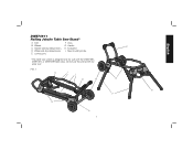
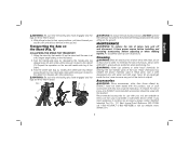
Wheel-side leg release levers E. Handle H. FIG. 1 C I I . Kickstand I D B H D G F E A 1 Legs G. Saw mounting holes * This table saw stand is designed only for use this stand with the DWE7490, DWE7491, or DWE7499 table saws. Locking pins F. Handle-side leg release levers D. English DWE74911 Rolling Jobsite Table Saw Stand* A. Axle B. Wheels C. Do not use with any other tool.
Wheel-side leg release levers E. Handle H. FIG. 1 C I I . Kickstand I D B H D G F E A 1 Legs G. Saw mounting holes * This table saw stand is designed only for use this stand with the DWE7490, DWE7491, or DWE7499 table saws. Locking pins F. Handle-side leg release levers D. English DWE74911 Rolling Jobsite Table Saw Stand* A. Axle B. Wheels C. Do not use with any other tool.
Instruction Manual
Page 4
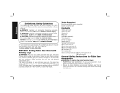
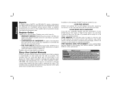
... in minor or moderate injury. Tools Required Hex key and small wrench (supplied) Socket or wrench set Contents Stand, right side Stand, left side Wheels (2) Rear axle Kickstand assembly Tube plugs (2) Handle assembly Handle feet (2) Carriage head bolts (2) M6x12 pan bolts (2) M8x40 hex head bolts (4) M8x40 pan head bolts (4) M8 lock nuts (12) Flat washers (2) Saw mounting hardware: M8x75 pan head bolts (4) M8 lock nuts (4) General Safety Instructions for Table Saw Accessories WARNING: To reduce the...
... in minor or moderate injury. Tools Required Hex key and small wrench (supplied) Socket or wrench set Contents Stand, right side Stand, left side Wheels (2) Rear axle Kickstand assembly Tube plugs (2) Handle assembly Handle feet (2) Carriage head bolts (2) M6x12 pan bolts (2) M8x40 hex head bolts (4) M8x40 pan head bolts (4) M8 lock nuts (12) Flat washers (2) Saw mounting hardware: M8x75 pan head bolts (4) M8 lock nuts (4) General Safety Instructions for Table Saw Accessories WARNING: To reduce the...
Instruction Manual
Page 5
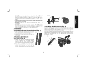
... pan bolts and nuts provided as shown. Install M6x12 pan head bolts until holes align. 2. Tighten wheel and axle nuts securely. Align the kickstand holes with the holes (N) in line with the holes on the axle (A) and secure with washers and lock nuts as shown. DO NOT use the stand on both sides. The DWE74911 table saw securely to be used on a flat, stable...
... pan bolts and nuts provided as shown. Install M6x12 pan head bolts until holes align. 2. Tighten wheel and axle nuts securely. Align the kickstand holes with the holes (N) in line with the holes on the axle (A) and secure with washers and lock nuts as shown. DO NOT use the stand on both sides. The DWE74911 table saw securely to be used on a flat, stable...
Instruction Manual
Page 6
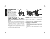
... workspace. Lift assembly by rotating leg release levers and rotate leg until locking pin clicks into the detent. WARNING: To reduce the risk of saw , table side down, on the end bracket. Unfold the handle side legs by depressing leg release levers and rotate until the saw and the accessory. 1. Install four nuts and tighten securely. NOTE: The handle has two positions to the table saw is fully...
... workspace. Lift assembly by rotating leg release levers and rotate leg until locking pin clicks into the detent. WARNING: To reduce the risk of saw , table side down, on the end bracket. Unfold the handle side legs by depressing leg release levers and rotate until the saw and the accessory. 1. Install four nuts and tighten securely. NOTE: The handle has two positions to the table saw is fully...
Instruction Manual
Page 7
... kickstand. 2. Recommended accessories for cleaning the non-metallic parts of all four feet are on the ground. WARNING: Never use of personal injury, DO NOT operate the table saw is at extra cost from power source before installing and removing accessories, before adjusting or when making repairs. never immerse any liquid get inside the tool; Fold the handle-side legs by DEWALT, have not been...
... kickstand. 2. Recommended accessories for cleaning the non-metallic parts of all four feet are on the ground. WARNING: Never use of personal injury, DO NOT operate the table saw is at extra cost from power source before installing and removing accessories, before adjusting or when making repairs. never immerse any liquid get inside the tool; Fold the handle-side legs by DEWALT, have not been...
Instruction Manual
Page 8
... warranty, DEWALT tools are covered by our: 1 YEAR FREE SERVICE DEWALT will maintain the tool and replace worn parts caused by normal use identical replacement parts. For further detail of purchase. Register Online Thank you may have been made or attempted by a DEWALT factory service center, a DEWALT authorized service center or other rights which vary in case there is required under the Federal Consumer Safety Act. Three Year Limited Warranty DEWALT...
... warranty, DEWALT tools are covered by our: 1 YEAR FREE SERVICE DEWALT will maintain the tool and replace worn parts caused by normal use identical replacement parts. For further detail of purchase. Register Online Thank you may have been made or attempted by a DEWALT factory service center, a DEWALT authorized service center or other rights which vary in case there is required under the Federal Consumer Safety Act. Three Year Limited Warranty DEWALT...
Instruction Manual
Page 24
DEWALT Industrial Tool Co., 701 East Joppa Road, Baltimore, MD 21286 (APR13) PART NO. the array of the tool. the kit box configuration; N272419 DW74911 Copyright © 2013 DEWALT The following are trademarks for one or more DEWALT power tools: the yellow and black color scheme; and the array of lozenge-shaped humps on the surface of pyramids on the handgrip; the "D" shaped air intake grill;
DEWALT Industrial Tool Co., 701 East Joppa Road, Baltimore, MD 21286 (APR13) PART NO. the array of the tool. the kit box configuration; N272419 DW74911 Copyright © 2013 DEWALT The following are trademarks for one or more DEWALT power tools: the yellow and black color scheme; and the array of lozenge-shaped humps on the surface of pyramids on the handgrip; the "D" shaped air intake grill;


