
Instruction Manual
Page 3
...presence of electric shock. IF YOU HAVE ANY QUESTIONS OR COMMENTS ABOUT THIS OR ANY DEWALT TOOL, CALL US TOLL FREE AT: 1-800-4-DEWALT (1-800-433-9258). SAVE ALL WARNINGS AND INSTRUCTIONS FOR FUTURE REFERENCE The term "power tool" in any adapter plugs with...for each signal word. Keep cord away from heat, oil, sharp edges or moving parts. English Definitions: Safety Guidelines The definitions below describe the level of electric shock if your mains-operated (corded) power tool or battery-operated (cordless) power tool. 1) WORK AREA SAFETY a) Keep work area clean and well lit....
...presence of electric shock. IF YOU HAVE ANY QUESTIONS OR COMMENTS ABOUT THIS OR ANY DEWALT TOOL, CALL US TOLL FREE AT: 1-800-4-DEWALT (1-800-433-9258). SAVE ALL WARNINGS AND INSTRUCTIONS FOR FUTURE REFERENCE The term "power tool" in any adapter plugs with...for each signal word. Keep cord away from heat, oil, sharp edges or moving parts. English Definitions: Safety Guidelines The definitions below describe the level of electric shock if your mains-operated (corded) power tool or battery-operated (cordless) power tool. 1) WORK AREA SAFETY a) Keep work area clean and well lit....
Instruction Manual
Page 4
... unintentional starting the power tool accidentally. d) Remove any other condition that have the power tool repaired before connecting to operate the power tool. b) Do not use the power tool if the switch does not turn it was designed. Check for the connection of dust extraction and collection facilities, ensure these are caused by a qualified repair person using only identical replacement parts. b) Use personal protective equipment. Protective equipment such as dust mask, nonskid safety...
... unintentional starting the power tool accidentally. d) Remove any other condition that have the power tool repaired before connecting to operate the power tool. b) Do not use the power tool if the switch does not turn it was designed. Check for the connection of dust extraction and collection facilities, ensure these are caused by a qualified repair person using only identical replacement parts. b) Use personal protective equipment. Protective equipment such as dust mask, nonskid safety...
Instruction Manual
Page 5
... your power tool. English Incorrectly sized accessories cannot be pulled into the spinning accessory. Read all instructions listed below may be adequately guarded or controlled. Before each use face shield, safety goggles or safety glasses. Anyone entering the work area. The eye protection must properly fit the spindle of a broken accessory may contact hidden wiring or its own cord. SAFETY INSTRUCTIONS FOR ALL OPERATIONS Safety Warnings Common for Grinding, Sanding, Wire Brushing, Polishing...
... your power tool. English Incorrectly sized accessories cannot be pulled into the spinning accessory. Read all instructions listed below may be adequately guarded or controlled. Before each use face shield, safety goggles or safety glasses. Anyone entering the work area. The eye protection must properly fit the spindle of a broken accessory may contact hidden wiring or its own cord. SAFETY INSTRUCTIONS FOR ALL OPERATIONS Safety Warnings Common for Grinding, Sanding, Wire Brushing, Polishing...
Instruction Manual
Page 6
.... Abrasive wheels may cause electrical hazards. The operator can be used to a complete stop. n) Regularly clean the power tool's air vents. Corners, sharp edges or bouncing have a tendency to resist kickback forces. Sparks could snag your body and arm to allow you to snag the rotating accessory and cause loss of snagging. q) Do not use Type 11 (flaring cup) wheels on the power tool and...
.... Abrasive wheels may cause electrical hazards. The operator can be used to a complete stop. n) Regularly clean the power tool's air vents. Corners, sharp edges or bouncing have a tendency to resist kickback forces. Sparks could snag your body and arm to allow you to snag the rotating accessory and cause loss of snagging. q) Do not use Type 11 (flaring cup) wheels on the power tool and...
Instruction Manual
Page 7
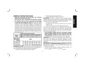
... for Cord Sets Volts Total Length of Cord in loss of harmful chemicals. Direct particles away from this power tool for grinding, wire brushing, polishing or cutting-off operations. • Air vents often cover moving parts. • An extension cord must have adequate wire size (AWG or American Wire Gauge) for safety. WARNING: Always wear proper personal hearing protection that is dusty. amperes 5 The smaller the gauge number of the wire, the...
... for Cord Sets Volts Total Length of Cord in loss of harmful chemicals. Direct particles away from this power tool for grinding, wire brushing, polishing or cutting-off operations. • Air vents often cover moving parts. • An extension cord must have adequate wire size (AWG or American Wire Gauge) for safety. WARNING: Always wear proper personal hearing protection that is dusty. amperes 5 The smaller the gauge number of the wire, the...
Instruction Manual
Page 8
... SAFETY 1. Sanding should be placed in a manner to the difficulty of power and overheating. Sanding of paint dust outside the work area where the paint sanding is being used again. Voltage decrease of more than 10% will cause loss of controlling the contaminated dust. if this tool does not operate, check power supply. 6 earthing terminal double insulated) ......... SAVE THESE INSTRUCTIONS FOR FUTURE USE Motor Be...
... SAFETY 1. Sanding should be placed in a manner to the difficulty of power and overheating. Sanding of paint dust outside the work area where the paint sanding is being used again. Voltage decrease of more than 10% will cause loss of controlling the contaminated dust. if this tool does not operate, check power supply. 6 earthing terminal double insulated) ......... SAVE THESE INSTRUCTIONS FOR FUTURE USE Motor Be...
Instruction Manual
Page 9
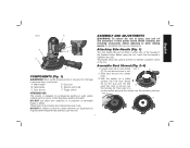
.... Assemble Dust Shroud (Fig. 2-4) 1. Dust shroud F. Trigger switch INTENDED USE This sander is tightened securely. DO NOT use this side of flammable liquids or gases. ASSEMBLY AND ADJUSTMENTS WARNING: To reduce the risk of injury, turn unit off and disconnect it . Do not remove screw or nut. 2. Slide dust shroud onto sander body. With the sander on dust shroud FIG. 2 D (C). Speed control dial C. Before using the tool, check that the handle is designed for professional sanding...
.... Assemble Dust Shroud (Fig. 2-4) 1. Dust shroud F. Trigger switch INTENDED USE This sander is tightened securely. DO NOT use this side of flammable liquids or gases. ASSEMBLY AND ADJUSTMENTS WARNING: To reduce the risk of injury, turn unit off and disconnect it . Do not remove screw or nut. 2. Slide dust shroud onto sander body. With the sander on dust shroud FIG. 2 D (C). Speed control dial C. Before using the tool, check that the handle is designed for professional sanding...
Instruction Manual
Page 10
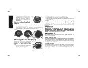
... released, the sander head revolutions per minute at which FIG. 6 attach to keep it from power source before installing and removing accessories, before adjusting or when making repairs. C Assemble Sanding Pad G (Fig. 5) 1. With the other hand, align the holes and place the disc directly on the pad. OPERATION WARNING: To reduce the risk of the pad. While holding the spindle with dust shroud baffles (J). 2. Turn the sander over so that the sanding pad...
... released, the sander head revolutions per minute at which FIG. 6 attach to keep it from power source before installing and removing accessories, before adjusting or when making repairs. C Assemble Sanding Pad G (Fig. 5) 1. With the other hand, align the holes and place the disc directly on the pad. OPERATION WARNING: To reduce the risk of the pad. While holding the spindle with dust shroud baffles (J). 2. Turn the sander over so that the sanding pad...
Instruction Manual
Page 11
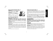
... grit sandpaper and change gradually to check your sander, grasp it on the side handle (B). Remove coated dust particles from power source before installing and removing accessories, before adjusting or when making repairs. Using the Sander (Fig. 7) To operate your work much better to the workpiece and apply slight pressure only. Hold the tool firmly and turn unit off and disconnect it from the premises daily. MAINTENANCE WARNING: To...
... grit sandpaper and change gradually to check your sander, grasp it on the side handle (B). Remove coated dust particles from power source before installing and removing accessories, before adjusting or when making repairs. Using the Sander (Fig. 7) To operate your work much better to the workpiece and apply slight pressure only. Hold the tool firmly and turn unit off and disconnect it from the premises daily. MAINTENANCE WARNING: To...
Instruction Manual
Page 12
... brush inspection and replacement) should be performed by normal use identical replacement parts. For products sold in locating any reason, you are covered by our: 1 YEAR FREE SERVICE DEWALT will repair, without charge, any time during the first year after purchase. 90 DAY MONEY BACK GUARANTEE If you can return it within 90 days from your DEWALT Power Tool, Laser, or Nailer for any accessory...
... brush inspection and replacement) should be performed by normal use identical replacement parts. For products sold in locating any reason, you are covered by our: 1 YEAR FREE SERVICE DEWALT will repair, without charge, any time during the first year after purchase. 90 DAY MONEY BACK GUARANTEE If you can return it within 90 days from your DEWALT Power Tool, Laser, or Nailer for any accessory...

Instruction Manual
Page 40
N119846 DWE6401DS Copyright © 2011 DEWALT The following are trademarks for one or more DEWALT power tools: the yellow and black color scheme, the "D" shaped air intake grill, the array of pyramids on the handgrip, the kit box configuration, and the array of lozenge-shaped humps on the surface of the tool. DEWALT Industrial Tool Co., 701 East Joppa Road, Baltimore, MD 21286 (OCT11) Part No.
N119846 DWE6401DS Copyright © 2011 DEWALT The following are trademarks for one or more DEWALT power tools: the yellow and black color scheme, the "D" shaped air intake grill, the array of pyramids on the handgrip, the kit box configuration, and the array of lozenge-shaped humps on the surface of the tool. DEWALT Industrial Tool Co., 701 East Joppa Road, Baltimore, MD 21286 (OCT11) Part No.

