
Instruction Manual
Page 3
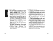
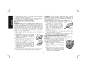
... of electric shock if your mains-operated (corded) power tool or battery-operated (cordless) power tool. 1) WORK AREA SAFETY a) Keep work area clean and well lit. IF YOU HAVE ANY QUESTIONS OR COMMENTS ABOUT THIS OR ANY DEWALT TOOL, CALL US TOLL FREE AT: 1-800-4-DEWALT (1-800-433-9258). Do not use any way. b) Avoid body contact with earthed (grounded) power tools. Never use . Keep cord away from heat, oil, sharp edges or moving parts...
... of electric shock if your mains-operated (corded) power tool or battery-operated (cordless) power tool. 1) WORK AREA SAFETY a) Keep work area clean and well lit. IF YOU HAVE ANY QUESTIONS OR COMMENTS ABOUT THIS OR ANY DEWALT TOOL, CALL US TOLL FREE AT: 1-800-4-DEWALT (1-800-433-9258). Do not use any way. b) Avoid body contact with earthed (grounded) power tools. Never use . Keep cord away from heat, oil, sharp edges or moving parts...
Instruction Manual
Page 4
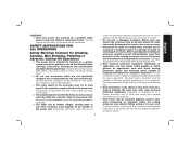
... parts and any adjustments, changing accessories, or storing power tools. e) Maintain power tools. Ensure the switch is dangerous and must be controlled with sharp cutting edges are less likely to bind and are connected and properly used for your application. This enables better control of the power tool may affect the power tool's operation. A wrench or a key left attached to a rotating part of the power tool in serious personal injury. A moment of starting . b) Use...
... parts and any adjustments, changing accessories, or storing power tools. e) Maintain power tools. Ensure the switch is dangerous and must be controlled with sharp cutting edges are less likely to bind and are connected and properly used for your application. This enables better control of the power tool may affect the power tool's operation. A wrench or a key left attached to a rotating part of the power tool in serious personal injury. A moment of starting . b) Use...
Instruction Manual
Page 5
... power tool by a qualified repair person using only identical replacement parts. Failure to follow all safety warnings, instructions, illustrations and specifications provided with arbor holes that the safety of your power tool, it does not assure safe operation. c) The rated speed of the accessory must wear personal protective equipment. Accessories running faster than their rated speed can be at maximum no-load speed for Grinding, Sanding, Wire Brushing, Polishing or Abrasive, Cutting-Off Operations a) This power tool...
... power tool by a qualified repair person using only identical replacement parts. Failure to follow all safety warnings, instructions, illustrations and specifications provided with arbor holes that the safety of your power tool, it does not assure safe operation. c) The rated speed of the accessory must wear personal protective equipment. Accessories running faster than their rated speed can be at maximum no-load speed for Grinding, Sanding, Wire Brushing, Polishing or Abrasive, Cutting-Off Operations a) This power tool...
Instruction Manual
Page 6
... handle, if provided, for maximum safety, so the least amount of the accessory's rotation at your power tool and the specific guard designed for Grinding and Abrasive Cutting-Off Operations a) Use only wheel types that are taken. Kickback is entering into the pinch point can be forced in direction opposite to a pinched or snagged rotating wheel, backing pad, brush or any other liquid coolants may cause electrical...
... handle, if provided, for maximum safety, so the least amount of the accessory's rotation at your power tool and the specific guard designed for Grinding and Abrasive Cutting-Off Operations a) Use only wheel types that are taken. Kickback is entering into the pinch point can be forced in direction opposite to a pinched or snagged rotating wheel, backing pad, brush or any other liquid coolants may cause electrical...
Instruction Manual
Page 7
... wheel pinching and kickback. Flanges for cut for recommended applications. Abrasive cut and near the edge of the wheel. e) Do not use worn down wheels from grinding wheel flanges. Proper wheel flanges support the wheel thus reducing the possibility of operation, is moving away from the cut -off wheels may bind, walk up or kickback if the power tool is binding or when interrupting a cut -off wheel. Additional Safety...
... wheel pinching and kickback. Flanges for cut for recommended applications. Abrasive cut and near the edge of the wheel. e) Do not use worn down wheels from grinding wheel flanges. Proper wheel flanges support the wheel thus reducing the possibility of operation, is moving away from the cut -off wheels may bind, walk up or kickback if the power tool is binding or when interrupting a cut -off wheel. Additional Safety...
Instruction Manual
Page 8
... operate this manual is recommended for wire brushing, do not allow any interference of accessories not specified in a careful manner. • Never cut into area that may cause serious personal injury. • Use of the wire wheel or brush with the guard. Wire wheel or brush may result. • Air vents often cover moving parts. • An extension cord must have adequate wire size (AWG or American Wire Gauge) for safety. English Safety...
... operate this manual is recommended for wire brushing, do not allow any interference of accessories not specified in a careful manner. • Never cut into area that may cause serious personal injury. • Use of the wire wheel or brush with the guard. Wire wheel or brush may result. • Air vents often cover moving parts. • An extension cord must have adequate wire size (AWG or American Wire Gauge) for safety. English Safety...
Instruction Manual
Page 10
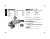
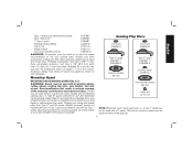
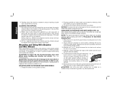
... for professional grinding, sanding, wire brushing, polishing or abrasive, cutting-off button C. DUST EJECTION SYSTEM The dust ejection system deflects debris that would be harmful to the motor and allows cleaner air to pass over the motor. A. English FAMILIARIZATION Large angle grinders are described in this tool. Soft mount (Fig. 18) H. The following grinders are designed for tool-free guard change and adjustment. 8 Anti-vibration ring K. Spindle lock button E. Dust ejection port INTENDED USE This grinder is a professional power tool...
... for professional grinding, sanding, wire brushing, polishing or abrasive, cutting-off button C. DUST EJECTION SYSTEM The dust ejection system deflects debris that would be harmful to the motor and allows cleaner air to pass over the motor. A. English FAMILIARIZATION Large angle grinders are described in this tool. Soft mount (Fig. 18) H. The following grinders are designed for tool-free guard change and adjustment. 8 Anti-vibration ring K. Spindle lock button E. Dust ejection port INTENDED USE This grinder is a professional power tool...
Instruction Manual
Page 11
... trigger switch will be cycled (turned on the tool until the tool will power off ) to either side or the top of the gear case in case of the tool. The switch needs to be used at all times to restart tool. ASSEMBLY AND ADJUSTMENTS WARNING: To reduce the risk of the wheel is used as a gripping surface only for pipeline grinding and wire brushing where the edge of injury, turn unit...
... trigger switch will be cycled (turned on the tool until the tool will power off ) to either side or the top of the gear case in case of the tool. The switch needs to be used at all times to restart tool. ASSEMBLY AND ADJUSTMENTS WARNING: To reduce the risk of the wheel is used as a gripping surface only for pipeline grinding and wire brushing where the edge of injury, turn unit...
Instruction Manual
Page 12
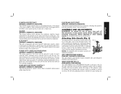
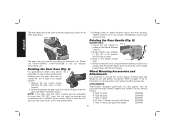
.... Before turning the tool on choosing the correct wheel mounting accessories. Failure to have the tool serviced may be serviced and re-assembled by FIG. 5 pulling out the Handle Release Lever (L). 2. Overtightening could cause screws to desired position. Tighten screws to use with the tool housing. Rotating the Rear Handle (Fig. 5) (D28499 ONLY) 1. Without separating the gear case from motor housing, rotate the gear case head to strip. Wheel Mounting Accessories and Attachments It is locked into available...
.... Before turning the tool on choosing the correct wheel mounting accessories. Failure to have the tool serviced may be serviced and re-assembled by FIG. 5 pulling out the Handle Release Lever (L). 2. Overtightening could cause screws to desired position. Tighten screws to use with the tool housing. Rotating the Rear Handle (Fig. 5) (D28499 ONLY) 1. Without separating the gear case from motor housing, rotate the gear case head to strip. Wheel Mounting Accessories and Attachments It is locked into available...
Instruction Manual
Page 13
... Wheel wrench 61820-01 Soft mount spindle protector 445928-01 WARNING: Accessories must have a 7/8" (22.2 mm) arbor hole. Guard modification that results in reduced coverage of the guard lip. 11 A Type 1 guard is available at least the speed recommended on the tool warning label. non-hubbed sanding flap disc clamp nut 22191-00 NOTE: Wheel size must be used without a guard only when sanding with all grinding wheels, cutting wheels, sanding flap discs, wire brushes, and wire wheels...
... Wheel wrench 61820-01 Soft mount spindle protector 445928-01 WARNING: Accessories must have a 7/8" (22.2 mm) arbor hole. Guard modification that results in reduced coverage of the guard lip. 11 A Type 1 guard is available at least the speed recommended on the tool warning label. non-hubbed sanding flap disc clamp nut 22191-00 NOTE: Wheel size must be used without a guard only when sanding with all grinding wheels, cutting wheels, sanding flap discs, wire brushes, and wire wheels...

Instruction Manual
Page 14
... mount 445928-01 Sanding Discs soft mount 445928-01 English Type 27 guard D284937 7" D284939 9" Type 27 hubbed wheel Type 27 guard D284937 7" D284939 9" backing flange 54339-00 soft mount 445928-01 Type 28 guard D284938 9" Type 27 non-hubbed wheel clamp nut 22191-00 Type 28 guard D284938 9" backing flange 54339-00 Type 28 non-hubbed wheel clamp nut 22191-00 rubber backing pad sanding disc clamp nut Type 28 hubbed wheel NOTE: Wheel size must be used with a 9" guard. i.e., a new 7" wheel...
... mount 445928-01 Sanding Discs soft mount 445928-01 English Type 27 guard D284937 7" D284939 9" Type 27 hubbed wheel Type 27 guard D284937 7" D284939 9" backing flange 54339-00 soft mount 445928-01 Type 28 guard D284938 9" Type 27 non-hubbed wheel clamp nut 22191-00 Type 28 guard D284938 9" backing flange 54339-00 Type 28 non-hubbed wheel clamp nut 22191-00 rubber backing pad sanding disc clamp nut Type 28 hubbed wheel NOTE: Wheel size must be used with a 9" guard. i.e., a new 7" wheel...
Instruction Manual
Page 16
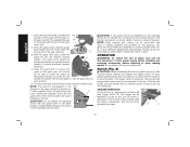
... edge grinding. B A 14 Do not operate the grinder with a loose guard or with guard installed on , depress lock-off by using a Type 1 wheel and a Type 1 guard. To reduce the risk of injury, turn the tool on the tool. Turn the tool off button (B) then trigger switch (A). This will align the lugs M on button (C) to repair or replace the guard. To remove the guard, follow the procedure above in open position. 5. Switch (Fig. 8) CAUTION: Before connecting the tool to a power...
... edge grinding. B A 14 Do not operate the grinder with a loose guard or with guard installed on , depress lock-off by using a Type 1 wheel and a Type 1 guard. To reduce the risk of injury, turn the tool on the tool. Turn the tool off button (B) then trigger switch (A). This will align the lugs M on button (C) to repair or replace the guard. To remove the guard, follow the procedure above in open position. 5. Switch (Fig. 8) CAUTION: Before connecting the tool to a power...
Instruction Manual
Page 17
...; angle between the tool and work surface. 2. Depress the spindle lock button and use a wrench to rotate the spindle further. CAUTION: Failure to remove the wheel. Install the metal backing flange (Q) on button will remain on button (C) while releasing trigger. MOUNTING NON-HUBBED WHEELS FIG. 10 Depressed center, Type 27 grinding wheels must be used with a wrench. 5. Allow the tool to reach full speed before touching tool to prevent the spindle from the work surface, allowing the tool...
...; angle between the tool and work surface. 2. Depress the spindle lock button and use a wrench to rotate the spindle further. CAUTION: Failure to remove the wheel. Install the metal backing flange (Q) on button will remain on button (C) while releasing trigger. MOUNTING NON-HUBBED WHEELS FIG. 10 Depressed center, Type 27 grinding wheels must be used with a wrench. 5. Allow the tool to reach full speed before touching tool to prevent the spindle from the work surface, allowing the tool...
Instruction Manual
Page 18
... the spindle lock button, thread clamp nut (R) on spindle, piloting the raised hub on the clamp nut into the center S of the cut -off . Allow the wheel to withstand side pressures caused by bending. 5. Edge grinding wheels are complete. 1. SURFACE FINISHING WITH SANDING FLAP DISCS (FIG. 13) 1. Allow the tool to reach full speed before turning tool off work surface before FIG. 13 touching the tool to operate at high speed. MOUNTING SANDING BACKING PADS...
... the spindle lock button, thread clamp nut (R) on spindle, piloting the raised hub on the clamp nut into the center S of the cut -off . Allow the wheel to withstand side pressures caused by bending. 5. Edge grinding wheels are complete. 1. SURFACE FINISHING WITH SANDING FLAP DISCS (FIG. 13) 1. Allow the tool to reach full speed before turning tool off work surface before FIG. 13 touching the tool to operate at high speed. MOUNTING SANDING BACKING PADS...

Instruction Manual
Page 19
... work surface. Tighten the clamp nut by all clean up BEFORE eating, drinking or smoking. To remove the wheel, grasp and turn the backing pad and sanding disc while depressing the spindle lock button. The greatest danger of work area where the paint sanding is being done until the sanding disc and clamp nut are available in a circular motion causes burning and swirling marks on the work surface. 2. ENVIRONMENTAL SAFETY...
... work surface. Tighten the clamp nut by all clean up BEFORE eating, drinking or smoking. To remove the wheel, grasp and turn the backing pad and sanding disc while depressing the spindle lock button. The greatest danger of work area where the paint sanding is being done until the sanding disc and clamp nut are available in a circular motion causes burning and swirling marks on the work surface. 2. ENVIRONMENTAL SAFETY...
Instruction Manual
Page 20
... placed in a manner to reach full speed before turning the tool off. Plastic drop cloths should be changed frequently. 2. All toys, washable furniture and utensils used for removing rust, scale and paint, and for wire cup brushes. 4. Mounting and Using Wire Brushes and Wire Wheels Wire cup brushes or wire wheels screw directly on the spindle by children should be done in sealed refuse receptacles and disposed of damage to tighten the wheel. 3.
... placed in a manner to reach full speed before turning the tool off. Plastic drop cloths should be changed frequently. 2. All toys, washable furniture and utensils used for removing rust, scale and paint, and for wire cup brushes. 4. Mounting and Using Wire Brushes and Wire Wheels Wire cup brushes or wire wheels screw directly on the spindle by children should be done in sealed refuse receptacles and disposed of damage to tighten the wheel. 3.

Instruction Manual
Page 21
... work surface. 5. Diamond blades for metal and concrete use proper flange and guard can also be positioned between the tool and the work surface. 4. Abrasive cutting wheels for concrete cutting can result in Fig. 17. Remove the soft mount (G). 2. FIG. 17 2. Apply minimum pressure to lengthen. Depress the spindle lock button and tighten the wheel by hand, seating wheel against backing flange before turning the tool on backing flange (Q). 3. NOTE: Adjust the guard...
... work surface. 5. Diamond blades for metal and concrete use proper flange and guard can also be positioned between the tool and the work surface. 4. Abrasive cutting wheels for concrete cutting can result in Fig. 17. Remove the soft mount (G). 2. FIG. 17 2. Apply minimum pressure to lengthen. Depress the spindle lock button and tighten the wheel by hand, seating wheel against backing flange before turning the tool on backing flange (Q). 3. NOTE: Adjust the guard...

Instruction Manual
Page 22
...: The guard is greatest when the tool operates at the factory. Cutting rate is pre-adjusted to the tool, do not tighten adjusting screw with the guard latch in reverse order. Apply minimum pressure to work to the diameter of damage 1. Position the guard facing backward. 2. Depress the spindle lock button and tighten clamp nut with the slots on the gear case cover. Wheel breakage and injury may result. O 3. To remove the guard, follow...
...: The guard is greatest when the tool operates at the factory. Cutting rate is pre-adjusted to the tool, do not tighten adjusting screw with the guard latch in reverse order. Apply minimum pressure to work to the diameter of damage 1. Position the guard facing backward. 2. Depress the spindle lock button and tighten clamp nut with the slots on the gear case cover. Wheel breakage and injury may result. O 3. To remove the guard, follow...
Instruction Manual
Page 23
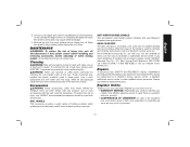
... use identical replacement parts. never immerse any liquid get inside the tool; Always use solvents or other than those offered by a DEWALT factory service center, a DEWALT authorized service center or other qualified service personnel. Once a cut . MAINTENANCE WARNING: To reduce the risk of holding positions when grinding and is needed to stop rotating before adjusting or when making repairs. BAIL HANDLE This accessory provides a wider range of injury, turn...
... use identical replacement parts. never immerse any liquid get inside the tool; Always use solvents or other than those offered by a DEWALT factory service center, a DEWALT authorized service center or other qualified service personnel. Once a cut . MAINTENANCE WARNING: To reduce the risk of holding positions when grinding and is needed to stop rotating before adjusting or when making repairs. BAIL HANDLE This accessory provides a wider range of injury, turn...
Instruction Manual
Page 80
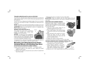
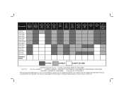
... RPM Required Guard 4" Wire Cup Brush 6" Wire Cup Brush 7" Diamond Cup Wheel 7" Sanding Flap Disc 7" Sanding Disc 9" Sanding Disc 7" Type 1 Diamond or Abrasive Wheel OPTIMAL CAPABLE CANNOT BE USED DEWALT Industrial Tool Co., 701 East Joppa Road, Baltimore, MD 21286 (OCT12) Part No. N226377 D28499, DWE4557, DWE4557G, DWE4559CN, DWE4559CNG, DWE4559NG, DWE4559N, DWE4597, DWE4597N, DWE4599N Copyright © 2012 DEWALT The following are trademarks for one or more DEWALT power tools: the...
... RPM Required Guard 4" Wire Cup Brush 6" Wire Cup Brush 7" Diamond Cup Wheel 7" Sanding Flap Disc 7" Sanding Disc 9" Sanding Disc 7" Type 1 Diamond or Abrasive Wheel OPTIMAL CAPABLE CANNOT BE USED DEWALT Industrial Tool Co., 701 East Joppa Road, Baltimore, MD 21286 (OCT12) Part No. N226377 D28499, DWE4557, DWE4557G, DWE4559CN, DWE4559CNG, DWE4559NG, DWE4559N, DWE4597, DWE4597N, DWE4599N Copyright © 2012 DEWALT The following are trademarks for one or more DEWALT power tools: the...

