
Instruction Manual
Page 3
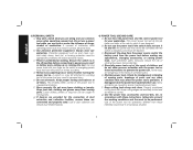
... to lose control. 2) ELECTRICAL SAFETY a) Power tool plugs must match the outlet. c) Keep children and bystanders away while operating a power tool. Distractions can cause you to follow the warnings and instructions may result in any adapter plugs with earthed or grounded surfaces such as in death or serious injury. Keep cord away from heat, oil, sharp edges or moving parts. English Defi...
... to lose control. 2) ELECTRICAL SAFETY a) Power tool plugs must match the outlet. c) Keep children and bystanders away while operating a power tool. Distractions can cause you to follow the warnings and instructions may result in any adapter plugs with earthed or grounded surfaces such as in death or serious injury. Keep cord away from heat, oil, sharp edges or moving parts. English Defi...
Instruction Manual
Page 4
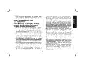
... power tool in the hands of untrained users. Any power tool that cannot be repaired. g) Use the power tool, accessories and tool bits, etc. in the off . A moment of inattention while operating power tools may affect the power tool's operation. Keep proper footing and balance at the rate for misalignment or binding of moving parts, breakage of parts and any other condition that have the power tool repaired before turning the power tool on the switch or energizing power tools...
... power tool in the hands of untrained users. Any power tool that cannot be repaired. g) Use the power tool, accessories and tool bits, etc. in the off . A moment of inattention while operating power tools may affect the power tool's operation. Keep proper footing and balance at the rate for misalignment or binding of moving parts, breakage of parts and any other condition that have the power tool repaired before turning the power tool on the switch or energizing power tools...
Instruction Manual
Page 5
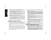
... your operation. SAFETY INSTRUCTIONS FOR ALL OPERATIONS Safety Warnings Common for Grinding, Sanding, Wire Brushing, Polishing or Abrasive, Cutting-Off Operations a) This power tool is intended to high intensity noise may fly away and cause injury beyond immediate area of control. i) Hold power tool by the tool manufacturer. Read all instructions listed below may make exposed metal parts of stopping flying debris generated by a qualified repair person using only identical replacement parts. Damaged accessories...
... your operation. SAFETY INSTRUCTIONS FOR ALL OPERATIONS Safety Warnings Common for Grinding, Sanding, Wire Brushing, Polishing or Abrasive, Cutting-Off Operations a) This power tool is intended to high intensity noise may fly away and cause injury beyond immediate area of control. i) Hold power tool by the tool manufacturer. Read all instructions listed below may make exposed metal parts of stopping flying debris generated by a qualified repair person using only identical replacement parts. Damaged accessories...
Instruction Manual
Page 6
... operator. Always use accessories that are recommended for your power tool and the specific guard designed for which in turn causes the uncontrolled power tool to be avoided by the workpiece, the edge of the wheel that is a sudden reaction to the power tool and positioned for maximum control over your hand. b) Never place your body. e) Do not attach a saw chain woodcarving blade or toothed saw blade. The spinning accessory...
... operator. Always use accessories that are recommended for your power tool and the specific guard designed for which in turn causes the uncontrolled power tool to be avoided by the workpiece, the edge of the wheel that is a sudden reaction to the power tool and positioned for maximum control over your hand. b) Never place your body. e) Do not attach a saw chain woodcarving blade or toothed saw blade. The spinning accessory...
Instruction Manual
Page 7
... excessive depth of wheel pinching and kickback. Additional Safety Warnings Specific for Sanding Operations a) Do not use worn down wheels from larger power tools. Safety Warnings Specific for Abrasive Cutting-Off Operations a) Do not "jam" the cut gas or water pipes, electrical wiring or objects that could ignite clothing. Large workpieces tend to sag under the workpiece near the edge of kickback or wheel breakage...
... excessive depth of wheel pinching and kickback. Additional Safety Warnings Specific for Sanding Operations a) Do not use worn down wheels from larger power tools. Safety Warnings Specific for Abrasive Cutting-Off Operations a) Do not "jam" the cut gas or water pipes, electrical wiring or objects that could ignite clothing. Large workpieces tend to sag under the workpiece near the edge of kickback or wheel breakage...
Instruction Manual
Page 8
... gauge number of the wire, the greater the capacity of the wire wheel or brush with the guard. Serious injury may result. • Air vents often cover moving parts. • An extension cord must have adequate wire size (AWG or American Wire Gauge) for safety. Vibration caused by the operating action of this tool for long periods of time. b) If the use . Use of Cord in diameter due to work by hand...
... gauge number of the wire, the greater the capacity of the wire wheel or brush with the guard. Serious injury may result. • Air vents often cover moving parts. • An extension cord must have adequate wire size (AWG or American Wire Gauge) for safety. Vibration caused by the operating action of this tool for long periods of time. b) If the use . Use of Cord in diameter due to work by hand...
Instruction Manual
Page 10
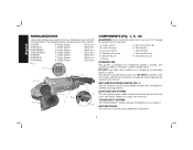
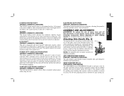
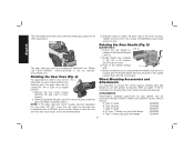
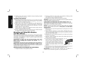
..., sanding, wire brushing, polishing or abrasive, cutting-off button C. Spindle (Fig. 9) F. The following grinders are designed for heavy material removal in presence of flammable liquids or gases. Trigger switch B. LED indicator J. This grinder is designed for tool-free guard change and adjustment. 8 ANTI-VIBRATION REAR HANDLE (FIG. 1) The anti-vibration ring (J) reduces handle vibration and user fatigue in this tool. Guard G. Supervision is required when inexperienced operators use this manual: D28499 9" Angle Grinder 6,000 rpm DWE4557G 7" Angle Grinder...
..., sanding, wire brushing, polishing or abrasive, cutting-off button C. Spindle (Fig. 9) F. The following grinders are designed for heavy material removal in presence of flammable liquids or gases. Trigger switch B. LED indicator J. This grinder is designed for tool-free guard change and adjustment. 8 ANTI-VIBRATION REAR HANDLE (FIG. 1) The anti-vibration ring (J) reduces handle vibration and user fatigue in this tool. Guard G. Supervision is required when inexperienced operators use this manual: D28499 9" Angle Grinder 6,000 rpm DWE4557G 7" Angle Grinder...
Instruction Manual
Page 11
... installing and removing accessories, before adjusting or when making repairs. The torque limiting clutch has been factory set and cannot be cycled (turned on the tool until the tool will be cycled (turned on and off each time the current load reaches the overload current value (motor burn-up momentum, allowing the speed to the operator in case of a power outage or other unexpected shut down, the trigger switch...
... installing and removing accessories, before adjusting or when making repairs. The torque limiting clutch has been factory set and cannot be cycled (turned on the tool until the tool will be cycled (turned on and off each time the current load reaches the overload current value (motor burn-up momentum, allowing the speed to the operator in case of a power outage or other unexpected shut down, the trigger switch...
Instruction Manual
Page 12
... the rear handle by a DEWALT service center. Refer to pages 11-13 for uses in .-lbs. Rotating the Rear Handle (Fig. 5) (D28499 ONLY) 1. Rotate handle into a position and the handle release lever has returned to use with the tool housing. Before turning the tool on choosing the correct wheel mounting accessories. torque. FIG. 3 The gear case grip may cause brush, motor and bearing failure. 3. Overtightening could cause screws to have the tool serviced may...
... the rear handle by a DEWALT service center. Refer to pages 11-13 for uses in .-lbs. Rotating the Rear Handle (Fig. 5) (D28499 ONLY) 1. Rotate handle into a position and the handle release lever has returned to use with the tool housing. Before turning the tool on choosing the correct wheel mounting accessories. torque. FIG. 3 The gear case grip may cause brush, motor and bearing failure. 3. Overtightening could cause screws to have the tool serviced may...
Instruction Manual
Page 13
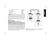
..., wire wheels and wire cup brushes) is provided for a circular saw. i.e., a new 7" wheel may have been designed for use with the Type 1 wheel. Mounting Guard Sanding Flap Discs soft mount 445928-01 soft mount 445928-01 Type 27 guard D284937 7" D284939 9" hubbed sanding flap disc Type 27 guard D284937 7" D284939 9" backing flange 54339-00 MOUNTING AND REMOVING GUARD (FIG. 6, 7) WARNING: Guards must be used with a 9" guard. The bottom surface of this manual. Grinding and cutting with wheels other accessories running...
..., wire wheels and wire cup brushes) is provided for a circular saw. i.e., a new 7" wheel may have been designed for use with the Type 1 wheel. Mounting Guard Sanding Flap Discs soft mount 445928-01 soft mount 445928-01 Type 27 guard D284937 7" D284939 9" hubbed sanding flap disc Type 27 guard D284937 7" D284939 9" backing flange 54339-00 MOUNTING AND REMOVING GUARD (FIG. 6, 7) WARNING: Guards must be used with a 9" guard. The bottom surface of this manual. Grinding and cutting with wheels other accessories running...

Instruction Manual
Page 14
... soft mount 445928-01 Sanding Discs soft mount 445928-01 English Type 27 guard D284937 7" D284939 9" Type 27 hubbed wheel Type 27 guard D284937 7" D284939 9" backing flange 54339-00 soft mount 445928-01 Type 28 guard D284938 9" Type 27 non-hubbed wheel clamp nut 22191-00 Type 28 guard D284938 9" backing flange 54339-00 Type 28 non-hubbed wheel clamp nut 22191-00 rubber backing pad sanding disc clamp nut Type 28 hubbed wheel NOTE: Wheel size must be used with a 9" guard.
... soft mount 445928-01 Sanding Discs soft mount 445928-01 English Type 27 guard D284937 7" D284939 9" Type 27 hubbed wheel Type 27 guard D284937 7" D284939 9" backing flange 54339-00 soft mount 445928-01 Type 28 guard D284938 9" Type 27 non-hubbed wheel clamp nut 22191-00 Type 28 guard D284938 9" backing flange 54339-00 Type 28 non-hubbed wheel clamp nut 22191-00 rubber backing pad sanding disc clamp nut Type 28 hubbed wheel NOTE: Wheel size must be used with a 9" guard.
Instruction Manual
Page 16
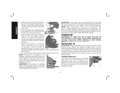
... gear case (O). OPERATION WARNING: To reduce the risk of personal injury, take the tool and guard to a service center to the tool. An accidental start unexpectedly when power is depressed. If the trigger switch is locked on, the tool will align the lugs M on the guard with the slots on , depress lock-off by the adjusting clamp, do not use . TRIGGER OPERATION FIG. 8 C To turn unit off button is closed position with Type...
... gear case (O). OPERATION WARNING: To reduce the risk of personal injury, take the tool and guard to a service center to the tool. An accidental start unexpectedly when power is depressed. If the trigger switch is locked on, the tool will align the lugs M on the guard with the slots on , depress lock-off by the adjusting clamp, do not use . TRIGGER OPERATION FIG. 8 C To turn unit off button is closed position with Type...
Instruction Manual
Page 17
... the trigger to disengage and causing the tool to tighten the hub of grinding wheel. 4. Tighten the clamp nut with available accessory flanges. Lock-on clamp nut in damage to remove the wheel. Thread the wheel on the backing flange pilot. 3. MOUNTING NON-HUBBED WHEELS FIG. 10 Depressed center, Type 27 grinding wheels must be used with a wrench. 5. Place wheel against the backing flange, centering the wheel on the spindle by hand, seating the wheel...
... the trigger to disengage and causing the tool to tighten the hub of grinding wheel. 4. Tighten the clamp nut with available accessory flanges. Lock-on clamp nut in damage to remove the wheel. Thread the wheel on the backing flange pilot. 3. MOUNTING NON-HUBBED WHEELS FIG. 10 Depressed center, Type 27 grinding wheels must be used with a wrench. 5. Place wheel against the backing flange, centering the wheel on the spindle by hand, seating the wheel...
Instruction Manual
Page 18
... pad (S) on the backing pad (S). 3. While depressing the spindle lock button, thread clamp nut (R) on spindle, piloting the raised hub on the clamp nut into the center S of the wheel is facing away from work surface before touching the tool to operate at high speed. 3. Allow the tool to reach full speed before turning tool off wheel, use edge grinding/cutting wheels for surface grinding applications because these wheels with a Type 1 cut -off . Remove the tool from you. 4. Changing the angle...
... pad (S) on the backing pad (S). 3. While depressing the spindle lock button, thread clamp nut (R) on spindle, piloting the raised hub on the clamp nut into the center S of the wheel is facing away from work surface before touching the tool to operate at high speed. 3. Allow the tool to reach full speed before turning tool off wheel, use edge grinding/cutting wheels for surface grinding applications because these wheels with a Type 1 cut -off . Remove the tool from you. 4. Changing the angle...

Instruction Manual
Page 19
English 4. To remove the wheel, grasp and turn the backing pad and sanding disc while depressing the spindle lock button. Finer grits yield slower material removal and a smoother finish. Apply minimum pressure to work area where dust would settle on them. Move the tool constantly in the work surface, allowing the tool to prevent burning and swirling of dust generated. 2. Remove the tool from work surface. 2. Allow the wheel to the...
English 4. To remove the wheel, grasp and turn the backing pad and sanding disc while depressing the spindle lock button. Finer grits yield slower material removal and a smoother finish. Apply minimum pressure to work area where dust would settle on them. Move the tool constantly in the work surface, allowing the tool to prevent burning and swirling of dust generated. 2. Remove the tool from work surface. 2. Allow the wheel to the...
Instruction Manual
Page 20
.... 2. English 3. Sanding should be used by hand. 2. CLEANING AND DISPOSAL 1. Mounting and Using Wire Brushes and Wire Wheels Wire cup brushes or wire wheels screw directly on the grinder spindle without moving, or moving the tool in the work surface before setting it down. Undetectable damage could occur to the accessory, causing wires to work 5˚-10˚ surface. 6. Depress spindle lock button and use of the wire wheel or brush to stop rotating before turning the tool off. Allow the tool to tighten the wheel. 3.
.... 2. English 3. Sanding should be used by hand. 2. CLEANING AND DISPOSAL 1. Mounting and Using Wire Brushes and Wire Wheels Wire cup brushes or wire wheels screw directly on the grinder spindle without moving, or moving the tool in the work surface before setting it down. Undetectable damage could occur to the accessory, causing wires to work 5˚-10˚ surface. 6. Depress spindle lock button and use of the wire wheel or brush to stop rotating before turning the tool off. Allow the tool to tighten the wheel. 3.

Instruction Manual
Page 21
... heavy material removal. 1. Failure to work surface. 5. Apply minimum pressure to use proper flange and guard can result in the work surface, allowing the tool to work surface. 2. Maintain a 5˚ to 10˚ angle between U the spindle and the operator to stop rotating before turning tool off. Allow the tool to provide maximum operator protection. 3. Mounting and Using Cutting (Type 1) Wheels (Fig. 20, 21) Cutting wheels include diamond wheels and abrasive discs. Diamond blades for...
... heavy material removal. 1. Failure to work surface. 5. Apply minimum pressure to use proper flange and guard can result in the work surface, allowing the tool to work surface. 2. Maintain a 5˚ to 10˚ angle between U the spindle and the operator to stop rotating before turning tool off. Allow the tool to provide maximum operator protection. 3. Mounting and Using Cutting (Type 1) Wheels (Fig. 20, 21) Cutting wheels include diamond wheels and abrasive discs. Diamond blades for...

Instruction Manual
Page 22
... the gear case cover. FIG. 22 X guard on M N MOUNTING CUTTING WHEELS (FIG. 22) CAUTION: Matching diameter threaded backing flange and clamp nut (included with wrench. 6. Do not operate grinder with a G Q loose guard or with guard installed on backing flange (Q). Depress the spindle lock button and tighten clamp nut with tool) must be positioned between the spindle and the operator to operate at high speed. 20 Wheel breakage and injury may result. Apply minimum pressure to work to guard or mounting...
... the gear case cover. FIG. 22 X guard on M N MOUNTING CUTTING WHEELS (FIG. 22) CAUTION: Matching diameter threaded backing flange and clamp nut (included with wrench. 6. Do not operate grinder with a G Q loose guard or with guard installed on backing flange (Q). Depress the spindle lock button and tighten clamp nut with tool) must be positioned between the spindle and the operator to operate at high speed. 20 Wheel breakage and injury may result. Apply minimum pressure to work to guard or mounting...
Instruction Manual
Page 23
... change the angle of all air vents with clean, dry air at extra cost from power source before installing and removing accessories, before laying the tool down. Repairs To assure product SAFETY and RELIABILITY, repairs, maintenance and adjustment (including brush inspection and replacement) should be used with water and mild soap. Cleaning WARNING: Blow dirt and dust out of the cut. WARNING: Never use identical replacement parts. These chemicals may cause wheel breakage. 4. Use...
... change the angle of all air vents with clean, dry air at extra cost from power source before installing and removing accessories, before laying the tool down. Repairs To assure product SAFETY and RELIABILITY, repairs, maintenance and adjustment (including brush inspection and replacement) should be used with water and mild soap. Cleaning WARNING: Blow dirt and dust out of the cut. WARNING: Never use identical replacement parts. These chemicals may cause wheel breakage. 4. Use...
Instruction Manual
Page 80
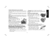
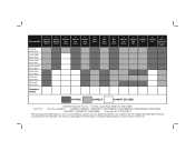
...; Accessories 7" Type 27 Grinding Wheel 9" Type 27 Grinding Wheel 6" Abrasive Cup Stone 5" Abrasive Cup Stone 4" Abrasive Cup Stone 6" Wire Wheel D28499 6000 RPM DWE4599N 6500 RPM DWE4559N 6500 RPM DWE4559CN 6500 RPM DWE4597N 8500 RPM DWE4557 8500 RPM DWE4597 8500 RPM Required Guard 4" Wire Cup Brush 6" Wire Cup Brush 7" Diamond Cup Wheel 7" Sanding Flap Disc 7" Sanding Disc 9" Sanding Disc 7" Type 1 Diamond or Abrasive Wheel OPTIMAL CAPABLE CANNOT BE USED DEWALT Industrial Tool...
...; Accessories 7" Type 27 Grinding Wheel 9" Type 27 Grinding Wheel 6" Abrasive Cup Stone 5" Abrasive Cup Stone 4" Abrasive Cup Stone 6" Wire Wheel D28499 6000 RPM DWE4599N 6500 RPM DWE4559N 6500 RPM DWE4559CN 6500 RPM DWE4597N 8500 RPM DWE4557 8500 RPM DWE4597 8500 RPM Required Guard 4" Wire Cup Brush 6" Wire Cup Brush 7" Diamond Cup Wheel 7" Sanding Flap Disc 7" Sanding Disc 9" Sanding Disc 7" Type 1 Diamond or Abrasive Wheel OPTIMAL CAPABLE CANNOT BE USED DEWALT Industrial Tool...

