Instruction Manual
Page 3
... ALL WARNINGS AND INSTRUCTIONS FOR FUTURE REFERENCE The term "power tool" in electric shock, fire and/or serious injury. c) Keep children and bystanders away while operating a power tool. c) Do not expose power tools to lose control. 2) ELECTRICAL SAFETY a) Power tool plugs must match the outlet. Keep cord away from heat, oil, sharp edges or moving parts. Damaged or entangled cords increase the risk of electric shock. 1 f) If operating a power tool in death...
... ALL WARNINGS AND INSTRUCTIONS FOR FUTURE REFERENCE The term "power tool" in electric shock, fire and/or serious injury. c) Keep children and bystanders away while operating a power tool. c) Do not expose power tools to lose control. 2) ELECTRICAL SAFETY a) Power tool plugs must match the outlet. Keep cord away from heat, oil, sharp edges or moving parts. Damaged or entangled cords increase the risk of electric shock. 1 f) If operating a power tool in death...
Instruction Manual
Page 4
... power tool on the switch or energizing power tools that cannot be controlled with the power tool or these instructions to operate the power tool. Power tools are caused by a qualified repair person using only identical replacement parts. Check for misalignment or binding of moving parts, breakage of parts and any adjusting key or wrench before use the power tool if the switch does not turn it was designed. Many accidents are dangerous in accordance with sharp cutting edges...
... power tool on the switch or energizing power tools that cannot be controlled with the power tool or these instructions to operate the power tool. Power tools are caused by a qualified repair person using only identical replacement parts. Check for misalignment or binding of moving parts, breakage of parts and any adjusting key or wrench before use the power tool if the switch does not turn it was designed. Many accidents are dangerous in accordance with sharp cutting edges...

Instruction Manual
Page 5
...-load speed for one minute. e) Threaded mounting of accessories must be capable of the accessory must wear personal protective equipment. Before each use a damaged accessory. The dust mask or respirator must match the grinder spindle thread. c) The rated speed of stopping flying debris generated by the tool manufacturer. f) Do not use inspect the accessory such as a grinder, sander, wire brush, polisher or cut-off tool. Depending on the power tool. English SAFETY INSTRUCTIONS FOR ALL OPERATIONS Safety...
...-load speed for one minute. e) Threaded mounting of accessories must be capable of the accessory must wear personal protective equipment. Before each use a damaged accessory. The dust mask or respirator must match the grinder spindle thread. c) The rated speed of stopping flying debris generated by the tool manufacturer. f) Do not use inspect the accessory such as a grinder, sander, wire brush, polisher or cut-off tool. Depending on the power tool. English SAFETY INSTRUCTIONS FOR ALL OPERATIONS Safety...
Instruction Manual
Page 6
... these materials. r) When starting the tool with a new or replacement wheel, or a new or replacement wire brush installed, hold the tool in injury. Abrasive wheels may lead to be used to a stable platform. Accidental contact with the wheel. Using water or other accessory. Never start the tool with a person in electrocution or shock. n) Do not operate the power tool near flammable materials. If the wire brush has loose wires, they will draw...
... these materials. r) When starting the tool with a new or replacement wheel, or a new or replacement wire brush installed, hold the tool in injury. Abrasive wheels may lead to be used to a stable platform. Accidental contact with the wheel. Using water or other accessory. Never start the tool with a person in electrocution or shock. n) Do not operate the power tool near flammable materials. If the wire brush has loose wires, they will draw...
Instruction Manual
Page 7
... wheel. Safety Warnings Specific for the higher speed of center depressed wheels must be securely attached to twisting or binding of the guard lip cannot be mounted below : a) Maintain a firm grip on the power tool and position your power tool and the specific guard designed for larger power tool is exposed towards the operator. b) Never place your hand. e) Do not attach a saw chain woodcarving blade or toothed saw blade...
... wheel. Safety Warnings Specific for the higher speed of center depressed wheels must be securely attached to twisting or binding of the guard lip cannot be mounted below : a) Maintain a firm grip on the power tool and position your power tool and the specific guard designed for larger power tool is exposed towards the operator. b) Never place your hand. e) Do not attach a saw chain woodcarving blade or toothed saw blade...

Instruction Manual
Page 8
... kickback if the power tool is restarted in motion otherwise kickback may cut and near the edge of the workpiece on the workpiece. Supports must be worn by applying excessive load to work and centrifugal forces. Safety Warnings Specific for wire brushing, do not allow any interference of these chemicals are within 50' (15.2 m) of the use of wheel binding. Tuck...
... kickback if the power tool is restarted in motion otherwise kickback may cut and near the edge of the workpiece on the workpiece. Supports must be worn by applying excessive load to work and centrifugal forces. Safety Warnings Specific for wire brushing, do not allow any interference of these chemicals are within 50' (15.2 m) of the use of wheel binding. Tuck...
Instruction Manual
Page 9
... ANSI Z87.1. • An extension cord must have adequate wire size (AWG WARNING: When not in serious personal injury. WARNING: Always use extra care the heavier the cord. The do this product may loosen total length, be easily knocked over. Direct particles away from power sanding, sawing, grinding, drilling, and other accessory contacts a secondary surface or a surface edge. 7 direct current W watts Class I Construction...
... ANSI Z87.1. • An extension cord must have adequate wire size (AWG WARNING: When not in serious personal injury. WARNING: Always use extra care the heavier the cord. The do this product may loosen total length, be easily knocked over. Direct particles away from power sanding, sawing, grinding, drilling, and other accessory contacts a secondary surface or a surface edge. 7 direct current W watts Class I Construction...

Instruction Manual
Page 10
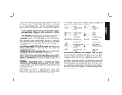
... 10 12 16 16 14 12 12 16 14 12 Not Recommended SAVE THESE INSTRUCTIONS FOR FUTURE USE COMPONENTS (Fig. 1) WARNING: Never modify the power tool or any part of it. Spindle (DWE402, DWE402G) F. Threaded locking flange I G D H F Spindle lock button K. Side handle FIG. 1 J E J 8 DWE402, DWE402N, DWE402G K I C A DWE4214 B I . Anti-lockup backing flange (DWE402, DWE402N, DWE402G) B. Slider switch (DWE4214) H. Damage or personal injury could result. Guard release lever D. A. Paddle switch G.
... 10 12 16 16 14 12 12 16 14 12 Not Recommended SAVE THESE INSTRUCTIONS FOR FUTURE USE COMPONENTS (Fig. 1) WARNING: Never modify the power tool or any part of it. Spindle (DWE402, DWE402G) F. Threaded locking flange I G D H F Spindle lock button K. Side handle FIG. 1 J E J 8 DWE402, DWE402N, DWE402G K I C A DWE4214 B I . Anti-lockup backing flange (DWE402, DWE402N, DWE402G) B. Slider switch (DWE4214) H. Damage or personal injury could result. Guard release lever D. A. Paddle switch G.

Instruction Manual
Page 11
... any adjustments or removing/installing attachments or accessories. INTENDED USE These heavy-duty small angle grinders have been designed for a circular saw. Before using the tool, check that the handle is important to choose the correct guards, backing pads and flanges to 20 in a dry protected area free from motor housing, rotate the gear case head to motor housing. 2. Tighten screws to use this tool is required when inexperienced operators use with grinder accessories. Accessories The capacity of power and...
... any adjustments or removing/installing attachments or accessories. INTENDED USE These heavy-duty small angle grinders have been designed for a circular saw. Before using the tool, check that the handle is important to choose the correct guards, backing pads and flanges to 20 in a dry protected area free from motor housing, rotate the gear case head to motor housing. 2. Tighten screws to use this tool is required when inexperienced operators use with grinder accessories. Accessories The capacity of power and...

Instruction Manual
Page 12
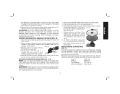
... accessory guards not included with a 1/4" (6.35 mm) thick Type 27 wheel. 4-1/2" (115 mm) Grinding Wheels Wire Wheels Sanding Discs English Type 27 guard Type 27 guard Type 27 guard Type 27 guard rubber backing pad unthreaded backing flange Type 27 hubbed wheel 3" (76.2 mm) wire cup brush 4" (100 mm) wire wheel sanding disc clamp nut Type 27 depressed center wheel threaded locking flange Mounting Guard CAUTION: Guards must be performed by using a Type 1 wheel and a Type 1 guard. Keeping the guard release lever open , align the lugs (L) on the gear case hub. A type...
... accessory guards not included with a 1/4" (6.35 mm) thick Type 27 wheel. 4-1/2" (115 mm) Grinding Wheels Wire Wheels Sanding Discs English Type 27 guard Type 27 guard Type 27 guard Type 27 guard rubber backing pad unthreaded backing flange Type 27 hubbed wheel 3" (76.2 mm) wire cup brush 4" (100 mm) wire wheel sanding disc clamp nut Type 27 depressed center wheel threaded locking flange Mounting Guard CAUTION: Guards must be performed by using a Type 1 wheel and a Type 1 guard. Keeping the guard release lever open , align the lugs (L) on the gear case hub. A type...

Instruction Manual
Page 13
... cutting wheel diamond cutting wheel threaded locking flange threaded locking flange * NOTE: A Type 1 guard is secure. 6. With the spindle facing the operator, rotate the guard clockwise into one of the guard. The guard body should snap into the desired working position. NOTE: The guard release lever should be rotated and adjusted by depressing the guard release lever. For easy adjustment, the guard can be rotated in the clockwise direction. The lever is only used for 11 removal...
... cutting wheel diamond cutting wheel threaded locking flange threaded locking flange * NOTE: A Type 1 guard is secure. 6. With the spindle facing the operator, rotate the guard clockwise into one of the guard. The guard body should snap into the desired working position. NOTE: The guard release lever should be rotated and adjusted by depressing the guard release lever. For easy adjustment, the guard can be rotated in the clockwise direction. The lever is only used for 11 removal...

Instruction Manual
Page 14
... use and until the wheel or accessory stops rotating. SLIDER SWITCH (FIG. 5) DWE4214 CAUTION: Before connecting the tool to the tool, such as described above after any interruption in power supply to a power supply, be performed with the grinder accessories. To start unexpectedly. To stop rotating before making any adjustments or removing/installing attachments or accessories. Ensure the switch is important to choose the correct guards and flanges to stop the tool, release...
... use and until the wheel or accessory stops rotating. SLIDER SWITCH (FIG. 5) DWE4214 CAUTION: Before connecting the tool to the tool, such as described above after any interruption in power supply to a power supply, be performed with the grinder accessories. To start unexpectedly. To stop rotating before making any adjustments or removing/installing attachments or accessories. Ensure the switch is important to choose the correct guards and flanges to stop the tool, release...

Instruction Manual
Page 15
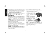
.... Operate the spindle lock button only when the tool is provided to a complete stop . G E 13 SPINDLE LOCK BUTTON (FIG. 7) FIG. 7 The spindle lock button (D) is D turned off . Place wheel against the wheel. To stop the tool while operating in extended use the correct guard per the instructions in injury. See pages 10 and 11 of the tool then depress the paddle switch (A). English For continuous operation, slide the switch (B) toward the back of this manual. FIG. 5 LOCK-ON BUTTON...
.... Operate the spindle lock button only when the tool is provided to a complete stop . G E 13 SPINDLE LOCK BUTTON (FIG. 7) FIG. 7 The spindle lock button (D) is D turned off . Place wheel against the wheel. To stop the tool while operating in extended use the correct guard per the instructions in injury. See pages 10 and 11 of the tool then depress the paddle switch (A). English For continuous operation, slide the switch (B) toward the back of this manual. FIG. 5 LOCK-ON BUTTON...

Instruction Manual
Page 16
... because the height of a Type 1 guard. 1. Reduce the depth of cutting/notching equal to avoid FIG. 10 creating gouges in the workpiece, do not change the angle of the wheel. Grinding rate is greatest when the tool operates at high speed. 3. Changing 14 If the wheel you . 4. To remove the wheel, depress the spindle lock button and loosen the threaded locking flange with a Type 1 wheel requires usage of the pilot...
... because the height of a Type 1 guard. 1. Reduce the depth of cutting/notching equal to avoid FIG. 10 creating gouges in the workpiece, do not change the angle of the wheel. Grinding rate is greatest when the tool operates at high speed. 3. Changing 14 If the wheel you . 4. To remove the wheel, depress the spindle lock button and loosen the threaded locking flange with a Type 1 wheel requires usage of the pilot...
Instruction Manual
Page 17
... clamp nut are available in the work surface. 4. To remove the wheel, grasp and O turn the backing pad and sanding pad while depressing the spindle lock button. Remove the tool from work surface before turning tool off . Continuously move the tool in a forward and back motion to avoid 5˚-10˚ creating gouges in various grits. Finer grits yield slower material removal and a smoother finish. WARNING: Do not use edge grinding/cutting wheels...
... clamp nut are available in the work surface. 4. To remove the wheel, grasp and O turn the backing pad and sanding pad while depressing the spindle lock button. Remove the tool from work surface before turning tool off . Continuously move the tool in a forward and back motion to avoid 5˚-10˚ creating gouges in various grits. Finer grits yield slower material removal and a smoother finish. WARNING: Do not use edge grinding/cutting wheels...

Instruction Manual
Page 18
... for working with D plastic sheeting of the wheel. 4. Thread the wheel on them. NOTICE: Failure to tighten the hub of 4 mils thickness. 3. Areas where paint removal is being done until all persons entering the work surface. where the paint sanding is occurring should be done in the work surface. Allowing the tool to minimize the amount of spindle. Depress the spindle lock button and use a wrench...
... for working with D plastic sheeting of the wheel. 4. Thread the wheel on them. NOTICE: Failure to tighten the hub of 4 mils thickness. 3. Areas where paint removal is being done until all persons entering the work surface. where the paint sanding is occurring should be done in the work surface. Allowing the tool to minimize the amount of spindle. Depress the spindle lock button and use a wrench...

Instruction Manual
Page 19
... adjustments or removing/installing attachments or accessories. Use only wire brushes or wheels provided with wire wheels. MOUNTING WIRE CUP BRUSHES AND WIRE WHEELS WARNING: To reduce the risk of flanges. Thread the wheel on the grinder spindle without the use of serious personal injury, turn tool off before being used again. USING WIRE CUP BRUSHES AND WIRE WHEELS (FIG. 16, 17) Wire wheels and brushes can be washed thoroughly before making any dust chips or other removal debris. Apply minimum pressure to work...
... adjustments or removing/installing attachments or accessories. Use only wire brushes or wheels provided with wire wheels. MOUNTING WIRE CUP BRUSHES AND WIRE WHEELS WARNING: To reduce the risk of flanges. Thread the wheel on the grinder spindle without the use of serious personal injury, turn tool off before being used again. USING WIRE CUP BRUSHES AND WIRE WHEELS (FIG. 16, 17) Wire wheels and brushes can be washed thoroughly before making any dust chips or other removal debris. Apply minimum pressure to work...
Instruction Manual
Page 20
... before making any adjustments or removing or installing attachments or accessories. Mounting and Using Type 1/Type 41 Cutting Wheels NOTE: The Type 1 guard MUST be used . Abrasive cutting wheels for metal and concrete use are available. Your grinder is required when using cutting wheels. Release the guard release lever. 4. For easy adjustment, the guard can also be used and is off . Press the guard release lever (J). 2. Keeping the guard release lever FIG. 18 L open , align the lugs (L) on the guard collar. Diamond blades for metal...
... before making any adjustments or removing or installing attachments or accessories. Mounting and Using Type 1/Type 41 Cutting Wheels NOTE: The Type 1 guard MUST be used . Abrasive cutting wheels for metal and concrete use are available. Your grinder is required when using cutting wheels. Release the guard release lever. 4. For easy adjustment, the guard can also be used and is off . Press the guard release lever (J). 2. Keeping the guard release lever FIG. 18 L open , align the lugs (L) on the guard collar. Diamond blades for metal...
Instruction Manual
Page 21
... the spindle lock button and tighten threaded locking flange with water and mild soap. Use a cloth dampened only with a wrench. MOUNTING TYPE 1 OR TYPE 41 CUTTING WHEELS 4. MAINTENANCE WARNING: To reduce the risk of grinding applications because these parts. at high speed. never immerse any liquid get inside the tool; To reduce the risk of injury, turn the tool to work surface before adjusting or when making any accessory, please contact DEWALT...
... the spindle lock button and tighten threaded locking flange with water and mild soap. Use a cloth dampened only with a wrench. MOUNTING TYPE 1 OR TYPE 41 CUTTING WHEELS 4. MAINTENANCE WARNING: To reduce the risk of grinding applications because these parts. at high speed. never immerse any liquid get inside the tool; To reduce the risk of injury, turn the tool to work surface before adjusting or when making any accessory, please contact DEWALT...

Instruction Manual
Page 22
... to normal wear or tool abuse. English Repairs To assure product SAFETY and RELIABILITY, repairs, maintenance and adjustment (including brush inspection and replacement) should be performed by others. This warranty does not cover part failure due to products sold in Latin America, see country specific warranty information contained in certain states or provinces. Register Online Thank you for : • WARRANTY SERVICE: Registering your product will...
... to normal wear or tool abuse. English Repairs To assure product SAFETY and RELIABILITY, repairs, maintenance and adjustment (including brush inspection and replacement) should be performed by others. This warranty does not cover part failure due to products sold in Latin America, see country specific warranty information contained in certain states or provinces. Register Online Thank you for : • WARRANTY SERVICE: Registering your product will...


