Instruction Manual
Page 3
... of normal safety precautions when operating this insulation system are removed from a possible electrical insulation failure within the tool. The temporary adapter should be kept at a safe distance from the adapter must be installed by the Canadian Electric Code. Double insulated tools are not completely understood, or if in doubt as a properly grounded outlet box. Repair or replace damaged or worn cord immediately NOTE...
... of normal safety precautions when operating this insulation system are removed from a possible electrical insulation failure within the tool. The temporary adapter should be kept at a safe distance from the adapter must be installed by the Canadian Electric Code. Double insulated tools are not completely understood, or if in doubt as a properly grounded outlet box. Repair or replace damaged or worn cord immediately NOTE...
Instruction Manual
Page 4
... switch does not turn it will do a job for lubricating and changing accessories. Loss of the blade. Additional Safety Rules for which it was not designed. The smaller the gauge number, the heavier the cord. Before further use the next heavier gauge. A guard or other part that the switch is equipped with a cord set -ups, when making repairs or changing locations. English • MAKE WORKSHOP CHILDPROOF with either hand...
... switch does not turn it will do a job for lubricating and changing accessories. Loss of the blade. Additional Safety Rules for which it was not designed. The smaller the gauge number, the heavier the cord. Before further use the next heavier gauge. A guard or other part that the switch is equipped with a cord set -ups, when making repairs or changing locations. English • MAKE WORKSHOP CHILDPROOF with either hand...
Instruction Manual
Page 5
... use of a miter gauge or rip fence or any cut -off and wait for repair. Knowledge is safety. • ADDITIONAL INFORMATION regarding the safe and proper operation of power tools (i.e., a safety video) is completely assembled and installed according to release. SAW BLADE GUARD AND SPLITTER Your table saw is running. KICKBACKS How to pass through the saw and keeps the operator's hands clear of the blade. • Kickback occurs when the saw blade binds in the cut...
... use of a miter gauge or rip fence or any cut -off and wait for repair. Knowledge is safety. • ADDITIONAL INFORMATION regarding the safe and proper operation of power tools (i.e., a safety video) is completely assembled and installed according to release. SAW BLADE GUARD AND SPLITTER Your table saw is running. KICKBACKS How to pass through the saw and keeps the operator's hands clear of the blade. • Kickback occurs when the saw blade binds in the cut...
Instruction Manual
Page 6
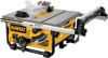
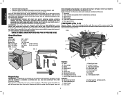
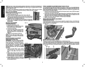
... approved safety equipment, such as shown in a well-ventilated area, and work . Miter gauge C. Dust collection port T. Rail lock lever Always use NIOSH/OSHA approved respiratory protection appropriate for proper dust removal. Blade guard E. Push stick 4 N K N J J. Fence F. Refer to saw base) 3. Blade guard 4. Table B. To reduce your mouth, eyes, or lay on how often you read and understand the entire instruction manual. Use dust collection system wherever possible. ON/OFF switch L. Blade height adjustment wheel FIGURE 4 R. Cord...
... approved safety equipment, such as shown in a well-ventilated area, and work . Miter gauge C. Dust collection port T. Rail lock lever Always use NIOSH/OSHA approved respiratory protection appropriate for proper dust removal. Blade guard E. Push stick 4 N K N J J. Fence F. Refer to saw base) 3. Blade guard 4. Table B. To reduce your mouth, eyes, or lay on how often you read and understand the entire instruction manual. Use dust collection system wherever possible. ON/OFF switch L. Blade height adjustment wheel FIGURE 4 R. Cord...
Instruction Manual
Page 7
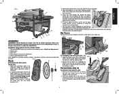
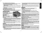
... 4. Blade height adjustment crank Tools needed for application) 5. Ensure that the outer washer and arbor nut are securely fastened against the washer as far as necessary until the nut and washer are free of the saw blade beveled to 45˚. Y 7. Reposition the wrench on the fence rail (F) with the fence head slot and align the latch (G) with the opening (BB). 2. Secure the rip fence by turning it , change the blade with your table saw . Remove...
... 4. Blade height adjustment crank Tools needed for application) 5. Ensure that the outer washer and arbor nut are securely fastened against the washer as far as necessary until the nut and washer are free of the saw blade beveled to 45˚. Y 7. Reposition the wrench on the fence rail (F) with the fence head slot and align the latch (G) with the opening (BB). 2. Secure the rip fence by turning it , change the blade with your table saw . Remove...
Instruction Manual
Page 8
... turns]. 4. Replace the throat plate. However, the wing nut must be in Figure 11. 4. In the event that additional adjustment is needed, extra guard shims have push stick ready to To Attach the Blade Guard under the table holding the guard retainer (GG) using a 5 mm hex wrench (HH), as shown in line with the DW745 mounts to the right of the saw blade arbor to Throat Plate.) 2. Remove the two screws...
... turns]. 4. Replace the throat plate. However, the wing nut must be in Figure 11. 4. In the event that additional adjustment is needed, extra guard shims have push stick ready to To Attach the Blade Guard under the table holding the guard retainer (GG) using a 5 mm hex wrench (HH), as shown in line with the DW745 mounts to the right of the saw blade arbor to Throat Plate.) 2. Remove the two screws...
Instruction Manual
Page 9
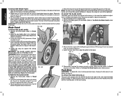
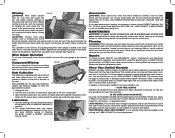
... injury, turn unit off and disconnect machine from power source before installing and removing H accessories, before connecting saw to power source, make sure the switch is in Figure 16. Be sure your saw OFF. English Miter Gauge NOTE: A large auxiliary miter gauge face may be used to anchor the table saw to your workbench or other rigid, stationary work support. NOTE: See crosscutting and bevel crosscutting instructions before use. Bench Mounting NOTE: A portable table saw stand...
... injury, turn unit off and disconnect machine from power source before installing and removing H accessories, before connecting saw to power source, make sure the switch is in Figure 16. Be sure your saw OFF. English Miter Gauge NOTE: A large auxiliary miter gauge face may be used to anchor the table saw to your workbench or other rigid, stationary work support. NOTE: See crosscutting and bevel crosscutting instructions before use. Bench Mounting NOTE: A portable table saw stand...
Instruction Manual
Page 10
... and blade assembly to the table at 0˚ and 45˚ to remove the screw (PP) holding the lock lever in the rip scale pointer with the miter slot. Tighten the locator screw and repeat on the left side of the saw, loosen the nut (LL) (Fig. 18). 3. Use a Phillips screwdriver to make sure blade does not hit the throat plate, causing personal injury. Once made, these directions...
... and blade assembly to the table at 0˚ and 45˚ to remove the screw (PP) holding the lock lever in the rip scale pointer with the miter slot. Tighten the locator screw and repeat on the left side of the saw, loosen the nut (LL) (Fig. 18). 3. Use a Phillips screwdriver to make sure blade does not hit the throat plate, causing personal injury. Once made, these directions...
Instruction Manual
Page 11
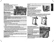
.... Keep hands clear of blades available to go against the square. Adjusting the Bevel Scale System (Fig. 22, 23) 1. If ripping, ensure fence lock lever is tight and fence is rotating. Tighten the screw against the stop cam (RR) until the work piece must have one straight, smooth side to do specific and special jobs such as cross cut off and disconnect machine from power source before installing and removing accessories...
.... Keep hands clear of blades available to go against the square. Adjusting the Bevel Scale System (Fig. 22, 23) 1. If ripping, ensure fence lock lever is tight and fence is rotating. Tighten the screw against the stop cam (RR) until the work piece must have one straight, smooth side to do specific and special jobs such as cross cut off and disconnect machine from power source before installing and removing accessories...

Instruction Manual
Page 12
...: NEVER use the fence as a cut to prevent binding of the work support. it falls off " side of the table. Adjust the blade height so that is ON and/or the saw motor and allow the blade to come up to speed. 5. Keep the work piece. While using a block as a guide or length stop on the free end of bevel angle. FIG. 28 10 Keep both hands to rip small pieces. CAUTION: Never...
...: NEVER use the fence as a cut to prevent binding of the work support. it falls off " side of the table. Adjust the blade height so that is ON and/or the saw motor and allow the blade to come up to speed. 5. Keep the work piece. While using a block as a guide or length stop on the free end of bevel angle. FIG. 28 10 Keep both hands to rip small pieces. CAUTION: Never...
Instruction Manual
Page 13
... as molding may require periodic cleaning and lubrication (Fig. 31). Compound Mitering This is a combination of purchase with the performance of your DEWALT Power Tool, Laser, or Nailer for warranty information. The height adjustment gear may not lift the guard properly. Cleaning WARNING: When cleaning, use identical replacement parts. Feed the work piece from power source before installing and removing accessories, before starting the motor, test the operation by others. An accidental start the cut. LATIN...
... as molding may require periodic cleaning and lubrication (Fig. 31). Compound Mitering This is a combination of purchase with the performance of your DEWALT Power Tool, Laser, or Nailer for warranty information. The height adjustment gear may not lift the guard properly. Cleaning WARNING: When cleaning, use identical replacement parts. Feed the work piece from power source before installing and removing accessories, before starting the motor, test the operation by others. An accidental start the cut. LATIN...
Instruction Manual
Page 44
DEWALT Industrial Tool Co., 701 Joppa Road, Baltimore, MD 21286 (JAN07) Form No. 650150-00 DW745 Copyright © 2006, 2007 DEWALT The following are trademarks for one or more DEWALT power tools: the yellow and black color scheme; the array of pyramids on the surface of lozenge-shaped humps on the handgrip; the kit box configuration; the "D" shaped air intake grill; and the array of the tool.
DEWALT Industrial Tool Co., 701 Joppa Road, Baltimore, MD 21286 (JAN07) Form No. 650150-00 DW745 Copyright © 2006, 2007 DEWALT The following are trademarks for one or more DEWALT power tools: the yellow and black color scheme; the array of pyramids on the surface of lozenge-shaped humps on the handgrip; the kit box configuration; the "D" shaped air intake grill; and the array of the tool.


