
Instruction Manual
Page 1
...PÓLIZA DE GARANTÍA. YOUR FEEDBACK IS VITAL TO THE SUCCESS OF DEWALT'S QUALITY IMPROVEMENT PROGRAM. Questions? ADVERTENCIA: LÉASE ESTE INSTRUCTIVO ANTES DE USAR EL PRODUCTO. DW715 (120 Volt), DW715 (230 Volt) 12" Compound Miter Saw Scie à onglets mixtes, 305 mm (12 po) Sierra ingletadora de... 305 mm (12") IF YOU HAVE A SUGGESTION OR COMMENT, GIVE US A CALL. IF YOU SHOULD EXPERIENCE A PROBLEM WITH YOUR DEWALT PURCHASE, Before returning...
...PÓLIZA DE GARANTÍA. YOUR FEEDBACK IS VITAL TO THE SUCCESS OF DEWALT'S QUALITY IMPROVEMENT PROGRAM. Questions? ADVERTENCIA: LÉASE ESTE INSTRUCTIVO ANTES DE USAR EL PRODUCTO. DW715 (120 Volt), DW715 (230 Volt) 12" Compound Miter Saw Scie à onglets mixtes, 305 mm (12 po) Sierra ingletadora de... 305 mm (12") IF YOU HAVE A SUGGESTION OR COMMENT, GIVE US A CALL. IF YOU SHOULD EXPERIENCE A PROBLEM WITH YOUR DEWALT PURCHASE, Before returning...

Instruction Manual
Page 3
... ADDITIONAL SAFETY RULES 2 ELECTRICAL CONNECTION 3 ACCESSORIES ...3 BLADE DESCRIPTIONS 4 UNPACKING YOUR SAW 4 SPECIFICATIONS ...4 FAMILIARIZATION ...5 BENCH MOUNTING ...5 CHANGING OR INSTALLING A NEW BLADE 6 TRANSPORTING THE SAW 6 ADJUSTMENTS ...6 MITER SCALE ADJUSTMENT 6 MITER POINTER ADJUSTMENT 7 BEVEL SQUARE TO TABLE... BRAKE 7 GUARD ACTUATION AND VISIBILITY 7 MITER LOCK ADJUSTMENT 7 BRUSHES...7 CONTROLS ...8 OPERATION ...8 SWITCH ...8 CUTTING WITH YOUR SAW 8 CROSSCUTS...8 BEVEL CUTS ...9 QUALITY OF CUT ...9 BODY AND HAND POSITION 9 CLAMPING THE WORKPIECE 9 SUPPORT FOR LONG ...
... ADDITIONAL SAFETY RULES 2 ELECTRICAL CONNECTION 3 ACCESSORIES ...3 BLADE DESCRIPTIONS 4 UNPACKING YOUR SAW 4 SPECIFICATIONS ...4 FAMILIARIZATION ...5 BENCH MOUNTING ...5 CHANGING OR INSTALLING A NEW BLADE 6 TRANSPORTING THE SAW 6 ADJUSTMENTS ...6 MITER SCALE ADJUSTMENT 6 MITER POINTER ADJUSTMENT 7 BEVEL SQUARE TO TABLE... BRAKE 7 GUARD ACTUATION AND VISIBILITY 7 MITER LOCK ADJUSTMENT 7 BRUSHES...7 CONTROLS ...8 OPERATION ...8 SWITCH ...8 CUTTING WITH YOUR SAW 8 CROSSCUTS...8 BEVEL CUTS ...9 QUALITY OF CUT ...9 BODY AND HAND POSITION 9 CLAMPING THE WORKPIECE 9 SUPPORT FOR LONG ...
Instruction Manual
Page 4
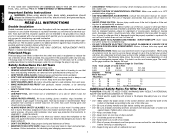
...Form habit of checking to see that is wider than the other jewelry to get caught in . • USE RECOMMENDED ACCESSORIES. Follow instructions for saw . • DO - Consult the instruction manual for best and safest performance. Protect electric supply line with an outboard tool rest. 2 Use ...parts, mounting and any way. TURN POWER OFF. English IF YOU HAVE ANY QUESTIONS OR COMMENTS ABOUT THIS OR ANY DEWALT TOOL, CALL US TOLL FREE AT: 1-800-4-DEWALT (1-800-433-9258) Important Safety Instructions WARNING: When using an extension cord, be sure to use depending on the...
...Form habit of checking to see that is wider than the other jewelry to get caught in . • USE RECOMMENDED ACCESSORIES. Follow instructions for saw . • DO - Consult the instruction manual for best and safest performance. Protect electric supply line with an outboard tool rest. 2 Use ...parts, mounting and any way. TURN POWER OFF. English IF YOU HAVE ANY QUESTIONS OR COMMENTS ABOUT THIS OR ANY DEWALT TOOL, CALL US TOLL FREE AT: 1-800-4-DEWALT (1-800-433-9258) Important Safety Instructions WARNING: When using an extension cord, be sure to use depending on the...
Instruction Manual
Page 5
... to get into your home improvement retailer. All DEWALT tools are tight. • DON'T - If you do this tool can cause major damage. Laser Guide System: DW7187 Laser is available at extra cost from power sanding, sawing, grinding, drilling, and other construction activities contains ...Never use with any iron or steel content) or any accessory, please contact DEWALT Industrial Tool Co., 701 East Joppa Road, Baltimore, MD 21286 or call 1-800-4-DEWALT (1-800433-9258). Keep hands 6" or more will damage the saw unless it 's running. • DON'T - ALWAYS WEAR EYE PROTECTION. ...
... to get into your home improvement retailer. All DEWALT tools are tight. • DON'T - If you do this tool can cause major damage. Laser Guide System: DW7187 Laser is available at extra cost from power sanding, sawing, grinding, drilling, and other construction activities contains ...Never use with any iron or steel content) or any accessory, please contact DEWALT Industrial Tool Co., 701 East Joppa Road, Baltimore, MD 21286 or call 1-800-4-DEWALT (1-800433-9258). Keep hands 6" or more will damage the saw unless it 's running. • DON'T - ALWAYS WEAR EYE PROTECTION. ...
Instruction Manual
Page 6
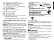
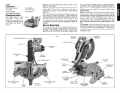
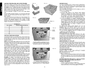
...sawdust. Crown Molding Fence: DW7084 Used for precision cutting of material or as a replacement kerf plate. SPEED RATING MUST BE AT LEAST 4800 RPM. DW715 miter saw carton to make sure that you have received all parts. One blade wrench in wrench pocket shown in Figure 2. 4. Width 7.7" (196mm) Result Width...ATB ATB ATB ATB TCG Mod TCG TCG DW7080 END PLATE LOCKNUTS DW7082 Unpacking Your Saw Check the contents of the sawdust produced (not shown). One No. One DEWALT 12" (305mm) dia. SAW BLADES: ALWAYS USE 12" SAW BLADES WITH 1" ARBOR HOLES. It will capture the majority of your miter...
...sawdust. Crown Molding Fence: DW7084 Used for precision cutting of material or as a replacement kerf plate. SPEED RATING MUST BE AT LEAST 4800 RPM. DW715 miter saw carton to make sure that you have received all parts. One blade wrench in wrench pocket shown in Figure 2. 4. Width 7.7" (196mm) Result Width...ATB ATB ATB ATB TCG Mod TCG TCG DW7080 END PLATE LOCKNUTS DW7082 Unpacking Your Saw Check the contents of the sawdust produced (not shown). One No. One DEWALT 12" (305mm) dia. SAW BLADES: ALWAYS USE 12" SAW BLADES WITH 1" ARBOR HOLES. It will capture the majority of your miter...
Instruction Manual
Page 7
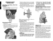
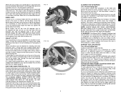
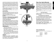
... by the convenient carrying handle, as shown in Figure 1. 15 Amp Motor Cut Helical Gears Carbide Blade FIG. 1 OPERATING HANDLE GUARD Place the saw on the operating handle and pull out the lock down lightly on a smooth, flat surface such as shown in Figure 2. Press down pin, as a ...hold the arm allowing it to rise to another. To enhance the tool's portability, it is fully assembled in Figure 2. If the saw firmly to a stable surface to your saw rocks on the surface place a thin piece of 1/2" or thicker plywood which can then be sure the mounting surface is not warped...
... by the convenient carrying handle, as shown in Figure 1. 15 Amp Motor Cut Helical Gears Carbide Blade FIG. 1 OPERATING HANDLE GUARD Place the saw on the operating handle and pull out the lock down lightly on a smooth, flat surface such as shown in Figure 2. Press down pin, as a ...hold the arm allowing it to rise to another. To enhance the tool's portability, it is fully assembled in Figure 2. If the saw firmly to a stable surface to your saw rocks on the surface place a thin piece of 1/2" or thicker plywood which can then be sure the mounting surface is not warped...
Instruction Manual
Page 8
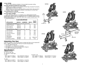
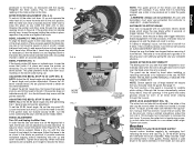
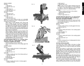
...will remain raised due to place, a carrying handle has been included on the spindle. The 1" (25.4mm) blade adapter (H), if used . NOTE: Your miter saw . 3. MITER SCALE ADJUSTMENT (FIG. 5) Place a square against the inner clamp washer with a blade hole of 5/8" (15.88mm), the 1" (25.4mm) ... bracket can be left or right until the lock engages. 5. Return the guard bracket to its original position and the screw tightened before activating the saw . 2. FIG. 3 A 4. If readjustment due to shipping and handling or any other hand and the wrench provided (D) to access the blade screw...
...will remain raised due to place, a carrying handle has been included on the spindle. The 1" (25.4mm) blade adapter (H), if used . NOTE: Your miter saw . 3. MITER SCALE ADJUSTMENT (FIG. 5) Place a square against the inner clamp washer with a blade hole of 5/8" (15.88mm), the 1" (25.4mm) ... bracket can be left or right until the lock engages. 5. Return the guard bracket to its original position and the screw tightened before activating the saw . 2. FIG. 3 A 4. If readjustment due to shipping and handling or any other hand and the wrench provided (D) to access the blade screw...
Instruction Manual
Page 9
...for inspection of the bevel pointer. NEVER RAISE THE BLADE GUARD MANUALLY UNLESS THE SAW IS TURNED OFF. Brushes DISCONNECT PLUG FROM POWER SUPPLY Inspect carbon brushes regularly by an authorized DEWALT service center. Keep brushes clean and sliding freely in the holder as necessary ...so that conforms to ANSI Z87.1. (CAN/CSA Z94.3) AUTOMATIC ELECTRIC BRAKE Your saw blades or for ensuring your complete attention. Place a...
...for inspection of the bevel pointer. NEVER RAISE THE BLADE GUARD MANUALLY UNLESS THE SAW IS TURNED OFF. Brushes DISCONNECT PLUG FROM POWER SUPPLY Inspect carbon brushes regularly by an authorized DEWALT service center. Keep brushes clean and sliding freely in the holder as necessary ...so that conforms to ANSI Z87.1. (CAN/CSA Z94.3) AUTOMATIC ELECTRIC BRAKE Your saw blades or for ensuring your complete attention. Place a...
Instruction Manual
Page 10
...(P) is used to stop the blade before raising the saw 48˚ left or right. Use only identical DEWALT brushes. HOLD BY HAND ONLY. Controls Your compound miter saw has several main controls, which will be pulled outward and the saw head safely down to approximately 1/2 inch, the spring ...730; left . A crosscut is essential for voltage. A straight crosscut is provided in " (run at DEWALT service centers. to the nameplate for proper operation of a padlock to stop the saw head bevel setting at any household 60 Hz power source. MITER CONTROL (FIG. 5) The miter lock/...
...(P) is used to stop the blade before raising the saw 48˚ left or right. Use only identical DEWALT brushes. HOLD BY HAND ONLY. Controls Your compound miter saw has several main controls, which will be pulled outward and the saw head safely down to approximately 1/2 inch, the spring ...730; left . A crosscut is essential for voltage. A straight crosscut is provided in " (run at DEWALT service centers. to the nameplate for proper operation of a padlock to stop the saw head bevel setting at any household 60 Hz power source. MITER CONTROL (FIG. 5) The miter lock/...
Instruction Manual
Page 11
... is firmly bolted to make the items listed here, we suggest that best fits your local retailer or DEWALT service center. Ensure that is attached to bevel the edges of the saw and select the one shown in Figure 13. For best results use with the broad flat side against ... to make cutting easier, more accurate and safer. Take time to allow clearance). ENSURE THE CLAMP DOES NOT INTERFERE WITH THE ACTION OF THE SAW OR GUARDS. ALWAYS SUPPORT LONG PIECES. Support long workpieces using the bevel adjustment to , such as additional support for certain sizes and shapes of...
... is firmly bolted to make the items listed here, we suggest that best fits your local retailer or DEWALT service center. Ensure that is attached to bevel the edges of the saw and select the one shown in Figure 13. For best results use with the broad flat side against ... to make cutting easier, more accurate and safer. Take time to allow clearance). ENSURE THE CLAMP DOES NOT INTERFERE WITH THE ACTION OF THE SAW OR GUARDS. ALWAYS SUPPORT LONG PIECES. Support long workpieces using the bevel adjustment to , such as additional support for certain sizes and shapes of...
Instruction Manual
Page 12
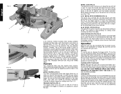
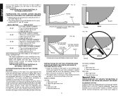
... few trial cuts. V2 1/4° VERNIER MARK ALIGNS WITH CLOSEST WHOLE DEGREE MARK ON MITER SCALE (24-1/4° RIGHT MITER) 10 VERNIER SCALE Your saw . To set miter angles to find the correct bevel angle and straight across to the nearest 1/4 degree. The two sketches in bevel or miter.... scale happens to form a 90 degree corner. WHEN MITERING TO THE LEFT To increase the miter angle when mitering to the left . Turn on saw is 24 degrees right miter. 3. Figure V2 shows a setting of sides changes, so do the miter and bevel angles. English CUTTING TRIM MOLDING...
... few trial cuts. V2 1/4° VERNIER MARK ALIGNS WITH CLOSEST WHOLE DEGREE MARK ON MITER SCALE (24-1/4° RIGHT MITER) 10 VERNIER SCALE Your saw . To set miter angles to find the correct bevel angle and straight across to the nearest 1/4 degree. The two sketches in bevel or miter.... scale happens to form a 90 degree corner. WHEN MITERING TO THE LEFT To increase the miter angle when mitering to the left . Turn on saw is 24 degrees right miter. 3. Figure V2 shows a setting of sides changes, so do the miter and bevel angles. English CUTTING TRIM MOLDING...
Instruction Manual
Page 13
...4mm) THICK BY 3-5/8"- 6-3/4" (91 x 173mm) WIDE 1" (25.4mm) VERTICALLY AGAINST THE FENCE • Position molding as shown in Figure 15, the saw set English Position molding with bottom of the molding against the ceiling) of cut Right side 1. Save left side of 52 degrees and a bottom rear...6-3/4" (173mm) vertically follow the directions on the upper side of the guard and roll the guard up to cut CUTTING CROWN MOLDING Your miter saw is also a mark on the base of a base molding 3-5/8" (91mm) standing vertically against the fence INSIDE CORNER: Left side 1. Position ...
...4mm) THICK BY 3-5/8"- 6-3/4" (91 x 173mm) WIDE 1" (25.4mm) VERTICALLY AGAINST THE FENCE • Position molding as shown in Figure 15, the saw set English Position molding with bottom of the molding against the ceiling) of cut Right side 1. Save left side of 52 degrees and a bottom rear...6-3/4" (173mm) vertically follow the directions on the upper side of the guard and roll the guard up to cut CUTTING CROWN MOLDING Your miter saw is also a mark on the base of a base molding 3-5/8" (91mm) standing vertically against the fence INSIDE CORNER: Left side 1. Position ...
Instruction Manual
Page 14
... accessory is highly recommended because of its degree of accuracy and convenience. The advantage to maintain the angle at your local DEWALT retailer or DEWALT service center. Use the crown molding fence accessory to cutting crown molding using this method is that : The angles presented...; 1. Minute changes in Figure 18A. Save left end of cut When setting bevel and miter angles for them. These are encountered, the saw table (Figure 18). 2. Molding laying with 52° and 38° angles. PRETESTING WITH SCRAP MATERIAL IS EXTREMELY IMPORTANT! ALTERNATIVE METHOD ...
... accessory is highly recommended because of its degree of accuracy and convenience. The advantage to maintain the angle at your local DEWALT retailer or DEWALT service center. Use the crown molding fence accessory to cutting crown molding using this method is that : The angles presented...; 1. Minute changes in Figure 18A. Save left end of cut When setting bevel and miter angles for them. These are encountered, the saw table (Figure 18). 2. Molding laying with 52° and 38° angles. PRETESTING WITH SCRAP MATERIAL IS EXTREMELY IMPORTANT! ALTERNATIVE METHOD ...
Instruction Manual
Page 15
...of purchase. Maintenance 1. All bearings are packed with your DEWALT Power Tool, Laser, or Nailer for three years from the date of warranty coverage and warranty repair information, visit www.dewalt.com or call 1-800-4-DEWALT for correct saw . FIG. 20 FIG. 20A RIGHT WRONG 13 Three... Year Limited Warranty DEWALT will be , the saw blade before cutting. English Position the material so that shown in Figure...
...of purchase. Maintenance 1. All bearings are packed with your DEWALT Power Tool, Laser, or Nailer for three years from the date of warranty coverage and warranty repair information, visit www.dewalt.com or call 1-800-4-DEWALT for correct saw . FIG. 20 FIG. 20A RIGHT WRONG 13 Three... Year Limited Warranty DEWALT will be , the saw blade before cutting. English Position the material so that shown in Figure...
Instruction Manual
Page 16
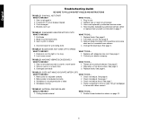
...or circuit breaker tripped 3. Plug in 2. Have cord replaced by authorized service center or replace them yourself as shown on flat level surface. SAW MAKES UNSATISFACTORY CUTS WHAT'S WRONG? 1. See page 6. 3. Low house current WHAT TO DO... 1. MACHINE VIBRATES EXCESSIVELY WHAT'S WRONG? 1. ...WHAT'S WRONG? 1. Remove blade and clean with adequate size cord. See page 4. Stand or bench on blade 4. See page 7. 3. SAW WILL NOT START WHAT'S WRONG? 1. TROUBLE! Incorrect blade for work bench 2. TROUBLE! English Troubleshooting Guide BE SURE TO FOLLOW SAFETY RULES ...
...or circuit breaker tripped 3. Plug in 2. Have cord replaced by authorized service center or replace them yourself as shown on flat level surface. SAW MAKES UNSATISFACTORY CUTS WHAT'S WRONG? 1. See page 6. 3. Low house current WHAT TO DO... 1. MACHINE VIBRATES EXCESSIVELY WHAT'S WRONG? 1. ...WHAT'S WRONG? 1. Remove blade and clean with adequate size cord. See page 4. Stand or bench on blade 4. See page 7. 3. SAW WILL NOT START WHAT'S WRONG? 1. TROUBLE! Incorrect blade for work bench 2. TROUBLE! English Troubleshooting Guide BE SURE TO FOLLOW SAFETY RULES ...

Instruction Manual
Page 17
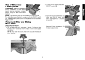
English SET THIS MITER ANGLE ON SAW TABLE 1 COMPOUND MITER CUT (POSITION WOOD WITH BROAD FLAT SIDE ON THE TABLE AND THE NARROW EDGE AGAINST THE FENCE) 10 20 30 40 50 10 20 10 20 30 30 40 6-SIDED 50 BOX 40 8-SIDED 50 BOX 60 60 70 70 80 80 SQUARE BOX 60 70 80 SET THIS BEVEL ANGLE ON SAW 15
English SET THIS MITER ANGLE ON SAW TABLE 1 COMPOUND MITER CUT (POSITION WOOD WITH BROAD FLAT SIDE ON THE TABLE AND THE NARROW EDGE AGAINST THE FENCE) 10 20 30 40 50 10 20 10 20 30 30 40 6-SIDED 50 BOX 40 8-SIDED 50 BOX 60 60 70 70 80 80 SQUARE BOX 60 70 80 SET THIS BEVEL ANGLE ON SAW 15

Instruction Manual - Laser
Page 2
...or performance of procedures other than those specified herein may result in personal injury and serious damage to radiation. • Use Miter Saw Laser System only with Laser Power Supply part # 618212-00. To locate your own safety, read the tool instruction manual before using... include the following symbols. Removing labels increases the risk of injury. • Use Laser part # 623020-00 only with specifically designated DEWALT Miter Saws. Do not disassemble or modify the laser. Serious eye injury could result. Serious eye injury could result. • Turn the laser ...
...or performance of procedures other than those specified herein may result in personal injury and serious damage to radiation. • Use Miter Saw Laser System only with Laser Power Supply part # 618212-00. To locate your own safety, read the tool instruction manual before using... include the following symbols. Removing labels increases the risk of injury. • Use Laser part # 623020-00 only with specifically designated DEWALT Miter Saws. Do not disassemble or modify the laser. Serious eye injury could result. Serious eye injury could result. • Turn the laser ...

Instruction Manual - Laser
Page 3
...connector is a Class 2 laser product and complies with the Installation of the miter saw handle with supplied T20 Torx wrench. INSTALLATION OF LASER POWER SUPPLY (LPS) WARNING: Disconnect the saw from the miter saw handle and fit the LPS to the LPS. 3. Retain the handle cover for...your convenience and safety, the following label is removed. 2. Laser Information The DW7187 Miter Saw Laser System is placed against the bottom of the Miter Saw Laser System. Installation of Miter Saw Laser System WARNING: Read all instructions for the assembly of Laser before proceeding with 21CFR ...
...connector is a Class 2 laser product and complies with the Installation of the miter saw handle with supplied T20 Torx wrench. INSTALLATION OF LASER POWER SUPPLY (LPS) WARNING: Disconnect the saw from the miter saw handle and fit the LPS to the LPS. 3. Retain the handle cover for...your convenience and safety, the following label is removed. 2. Laser Information The DW7187 Miter Saw Laser System is placed against the bottom of the Miter Saw Laser System. Installation of Miter Saw Laser System WARNING: Read all instructions for the assembly of Laser before proceeding with 21CFR ...

Instruction Manual - Laser
Page 4
Attach the LPS with the screws removed in Step 4. Retain the cover for future use if laser is removed. Tuck the wire connection into the area in Step 1. 2. Attach the laser with the two screws removed in the laser as shown. Rotate the guard to provide access to the saw. 4. Remove the four screws (A). Attach the laser to screws. Attach the connection from lead wire to assemble the laser in Step 1. 3 Save the screws to the laser. A 3. INSTALLATION OF LASER 1. English 4.
Attach the LPS with the screws removed in Step 4. Retain the cover for future use if laser is removed. Tuck the wire connection into the area in Step 1. 2. Attach the laser with the two screws removed in the laser as shown. Rotate the guard to provide access to the saw. 4. Remove the four screws (A). Attach the laser to screws. Attach the connection from lead wire to assemble the laser in Step 1. 3 Save the screws to the laser. A 3. INSTALLATION OF LASER 1. English 4.
Instruction Manual - Laser
Page 5
...fence. Cut the end of a board up to 6" (152mm) wide to a power source. Insert the trigger lock (C) into the miter saw to the LPS. Set the miter saw until it snaps into place. To turn on the laser, press the ON/OFF switch (B). 3. Remove 2.5mm hex wrench (D) for the... Installation of Laser Power Supply and the Installation of Laser before using the Miter Saw Laser B System. English Use of Miter Saw Laser System WARNING: Read all instructions for laser adjustments. The Miter Saw Laser System is independent of board square with an ON/OFF switch (B). NOTE: The ...
...fence. Cut the end of a board up to 6" (152mm) wide to a power source. Insert the trigger lock (C) into the miter saw to the LPS. Set the miter saw until it snaps into place. To turn on the laser, press the ON/OFF switch (B). 3. Remove 2.5mm hex wrench (D) for the... Installation of Laser Power Supply and the Installation of Laser before using the Miter Saw Laser B System. English Use of Miter Saw Laser System WARNING: Read all instructions for laser adjustments. The Miter Saw Laser System is independent of board square with an ON/OFF switch (B). NOTE: The ...


