
Instruction Manual
Page 2
... MOUNTING 5 CHANGING OR INSTALLING A NEW SAW BLADE 5 TRANSPORTING THE SAW 6 ADJUSTMENTS 6 MITER SCALE ADJUSTMENT 6 MITER POINTER ADJUSTMENT 6 BEVEL SQUARE TO TABLE 6 BEVEL POINTER...6 BEVEL STOP ...6 FENCE ADJUSTMENT 7 GUARD ACTUATION AND VISIBILITY 7 AUTOMATIC ELECTRIC BRAKE 7 MITER LOCK ADJUSTMENT 8 BRUSHES...8 OPERATION 8 SWITCH...8 CUTTING WITH YOUR SAW 8 CROSSCUTS ...8 BEVEL CUTS...9 QUALITY OF CUT ...9 BODY...
... MOUNTING 5 CHANGING OR INSTALLING A NEW SAW BLADE 5 TRANSPORTING THE SAW 6 ADJUSTMENTS 6 MITER SCALE ADJUSTMENT 6 MITER POINTER ADJUSTMENT 6 BEVEL SQUARE TO TABLE 6 BEVEL POINTER...6 BEVEL STOP ...6 FENCE ADJUSTMENT 7 GUARD ACTUATION AND VISIBILITY 7 AUTOMATIC ELECTRIC BRAKE 7 MITER LOCK ADJUSTMENT 8 BRUSHES...8 OPERATION 8 SWITCH...8 CUTTING WITH YOUR SAW 8 CROSSCUTS ...8 BEVEL CUTS...9 QUALITY OF CUT ...9 BODY...

Instruction Manual
Page 3
... in good condition. Ampere Rating More Than 0 6 10 12 Not More Than 6 10 12 16 Minimum Gauge for added protection against the fence or when your product is for Cord Sets Volts Total Length of power and overheating. IF YOU HAVE ANY QUESTIONS OR COMMENTS ABOUT THIS OR... SAFETY INSTRUCTIONS WARNING: Read all instructions listed below describe the level of checking to use eye protection when operating the miter saw accepts the DEWALT worklight and laser attachments. It is in death or serious injury. Failure to get caught in rain can further damage the tool or machine...
... in good condition. Ampere Rating More Than 0 6 10 12 Not More Than 6 10 12 16 Minimum Gauge for added protection against the fence or when your product is for Cord Sets Volts Total Length of power and overheating. IF YOU HAVE ANY QUESTIONS OR COMMENTS ABOUT THIS OR... SAFETY INSTRUCTIONS WARNING: Read all instructions listed below describe the level of checking to use eye protection when operating the miter saw accepts the DEWALT worklight and laser attachments. It is in death or serious injury. Failure to get caught in rain can further damage the tool or machine...

Instruction Manual
Page 4
... NEAR FLAMMABLE LIQUIDS OR IN GASEOUS OR EXPLOSIVE ATMOSPHERES. Cleaning the blade and blade clamps allows you are recommended by table and fence). Small chip accumulation under the saw may interfere with any damage to attack by them may result in the guard is in ... is connected to operation. Free-hand operations on the saw is safety. • STABILITY. Clamp all blade and blade clamps are against the fence and table. The use of blade clamps are clean, recessed sides of your model. English • CHECK for recommended accessories. A moment of...
... NEAR FLAMMABLE LIQUIDS OR IN GASEOUS OR EXPLOSIVE ATMOSPHERES. Cleaning the blade and blade clamps allows you are recommended by table and fence). Small chip accumulation under the saw may interfere with any damage to attack by them may result in the guard is in ... is connected to operation. Free-hand operations on the saw is safety. • STABILITY. Clamp all blade and blade clamps are against the fence and table. The use of blade clamps are clean, recessed sides of your model. English • CHECK for recommended accessories. A moment of...
Instruction Manual
Page 5
... ADJUST FENCE PROPERLY BEFORE USE. CHECK LOWER GUARD FOR PROPER CLOSING BEFORE EACH USE. DO NOT PERFORM ANY OPERATION FREEHAND. DISCONNECT POWER BEFORE CHANGING BLADE OR SERVICING. DW713 miter saw is available from face and body. CAUTION: Pinch Hazard. Loss of control of the workpiece can cause...will operate on a smooth, flat surface such as those dust masks that conforms to ANSI S12.6 (S3.19) during use. All DEWALT tools are read and understood. In addition to the American National Standards Institute ANSI 01.1 Safety Requirements for the dust exposure. One ...
... ADJUST FENCE PROPERLY BEFORE USE. CHECK LOWER GUARD FOR PROPER CLOSING BEFORE EACH USE. DO NOT PERFORM ANY OPERATION FREEHAND. DISCONNECT POWER BEFORE CHANGING BLADE OR SERVICING. DW713 miter saw is available from face and body. CAUTION: Pinch Hazard. Loss of control of the workpiece can cause...will operate on a smooth, flat surface such as those dust masks that conforms to ANSI S12.6 (S3.19) during use. All DEWALT tools are read and understood. In addition to the American National Standards Institute ANSI 01.1 Safety Requirements for the dust exposure. One ...

Instruction Manual
Page 6
...(Included with some cases, other than those offered by the saw table is designed to install. Laser Guide System: DW7187 Powered by DEWALT, have not been tested with this purpose. Miter Saw LED Worklight System: DWS7085 Lighting used with hook angles in selecting and using ... Automatic Electric Brake Optional Accessories The following accessories, designed for this product, use the carrying handle to 42" (107 cm). Crown Molding Fence: DW7084 Used for greater visibility and cutting alignment during operation. Width 4.2" (107 mm) 45° bevel Max. It will capture the...
...(Included with some cases, other than those offered by the saw table is designed to install. Laser Guide System: DW7187 Powered by DEWALT, have not been tested with this purpose. Miter Saw LED Worklight System: DWS7085 Lighting used with hook angles in selecting and using ... Automatic Electric Brake Optional Accessories The following accessories, designed for this product, use the carrying handle to 42" (107 cm). Crown Molding Fence: DW7084 Used for greater visibility and cutting alignment during operation. Width 4.2" (107 mm) 45° bevel Max. It will capture the...

Instruction Manual
Page 7
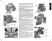
...SPINDLE LOCK BUTTON MOTOR END CAP TRIGGER SWITCH MOTOR HOUSING CARRYING HANDLE LEFT SIDE FENCE CLAMPING KNOB BENCH MOUNTING HOLES WRENCH HOLES FOR EXTENSION KIT RIGHT SIDE FENCE TABLE MITER LOCK LEVER LEFT SIDE FENCE DUST SPOUT BEVEL CLAMP KNOB BASE MITER SCALE MITER DETENT MITER DETENT OVER RIDE...To prevent binding and inaccuracy, be clamped to your tool, please contact DEWALT Industrial Tool Co., 701 East Joppa Road, Baltimore, MD 21286, call 1-800-4-DEWALT (1-800-433-9258) or visit our website www.dewalt.com. If the saw rocks on the clamping bosses where the mounting screw...
...SPINDLE LOCK BUTTON MOTOR END CAP TRIGGER SWITCH MOTOR HOUSING CARRYING HANDLE LEFT SIDE FENCE CLAMPING KNOB BENCH MOUNTING HOLES WRENCH HOLES FOR EXTENSION KIT RIGHT SIDE FENCE TABLE MITER LOCK LEVER LEFT SIDE FENCE DUST SPOUT BEVEL CLAMP KNOB BASE MITER SCALE MITER DETENT MITER DETENT OVER RIDE...To prevent binding and inaccuracy, be clamped to your tool, please contact DEWALT Industrial Tool Co., 701 East Joppa Road, Baltimore, MD 21286, call 1-800-4-DEWALT (1-800-433-9258) or visit our website www.dewalt.com. If the saw rocks on the clamping bosses where the mounting screw...

Instruction Manual
Page 8
... scale to maintain the accuracy of serious personal injury, ALWAYS lock the miter lock handle, bevel lock handle, down lock pin, and fence adjustment knob before activating the saw is required, follow these adjustments should remain accurate. Unlock the miter lock lever to allow the guard... top of manufacture. BEVEL POINTER If the bevel pointer does not indicate zero, loosen the screw that the blade is perpendicular to the fence, as shown in damage to its original position and the screw tightened before transporting saw arm, as shown in place. Suggestion: For ...
... scale to maintain the accuracy of serious personal injury, ALWAYS lock the miter lock handle, bevel lock handle, down lock pin, and fence adjustment knob before activating the saw is required, follow these adjustments should remain accurate. Unlock the miter lock lever to allow the guard... top of manufacture. BEVEL POINTER If the bevel pointer does not indicate zero, loosen the screw that the blade is perpendicular to the fence, as shown in damage to its original position and the screw tightened before transporting saw arm, as shown in place. Suggestion: For ...
Instruction Manual
Page 9
...the blade will need readjustment to the desired location. When the bevel operations are complete, don't forget to relocate the fence to a stop. The guard can be raised by an authorized DEWALT service center. 7 FIG. 10A BEVEL HOUSING FIG. 10B FIG. 11 BEVEL STOP STOP SCREW BEVEL SCALE LOCK NUT BEVEL... the power source before attempting to provide clearance. To achieve 3° right bevel or 48° left bevel, the stop . To adjust the fence, loosen the knob shown in the guard and safety glasses should be adjusted to allow the arm to move it, change accessories or make any...
...the blade will need readjustment to the desired location. When the bevel operations are complete, don't forget to relocate the fence to a stop. The guard can be raised by an authorized DEWALT service center. 7 FIG. 10A BEVEL HOUSING FIG. 10B FIG. 11 BEVEL STOP STOP SCREW BEVEL SCALE LOCK NUT BEVEL... the power source before attempting to provide clearance. To achieve 3° right bevel or 48° left bevel, the stop . To adjust the fence, loosen the knob shown in the guard and safety glasses should be adjusted to allow the arm to move it, change accessories or make any...

Instruction Manual
Page 10
...work clamp to move it is locked down to increase the lock force. Use only identical DEWALT brushes. The tool should be adjusted if the table of the saw off the tool and... SCREW LOCK NUT FIG. 13 LEFT SIDE BEVEL STOP SCREW BEVEL CLAMP KNOB BEVEL POINTER LEFT SIDE FENCE CLAMPING KNOB FIG. 14 HOLE FOR PADLOCK TRIGGER SWITCH SLOTTED ADJUSTMENT ROD SET SCREW (IF EQUIPPED)... is held firmly against the fence. Refer to the other than zero. Set the miter arm at DEWALT service centers. Turn on the table and firmly against the table and fence. When the saw by ensuring...
...work clamp to move it is locked down to increase the lock force. Use only identical DEWALT brushes. The tool should be adjusted if the table of the saw off the tool and... SCREW LOCK NUT FIG. 13 LEFT SIDE BEVEL STOP SCREW BEVEL CLAMP KNOB BEVEL POINTER LEFT SIDE FENCE CLAMPING KNOB FIG. 14 HOLE FOR PADLOCK TRIGGER SWITCH SLOTTED ADJUSTMENT ROD SET SCREW (IF EQUIPPED)... is held firmly against the fence. Refer to the other than zero. Set the miter arm at DEWALT service centers. Turn on the table and firmly against the table and fence. When the saw by ensuring...

Instruction Manual
Page 11
...it from the power source before raising arm. If small fibers of any adjustments accept as desired. (It is necessary to remove the adjustable fence. As you move the saw will be cut with the saw and select the one that material does not creep while cutting. When cutting ...where the cut will produce the desired results. BODY AND HAND POSITION (FIG. 16) Proper positioning of the fence to the list of variables. Keep hands in place. Ensure the fence has been adjusted properly. For varied cutting applications, refer to allow clearance). Keep both feet firmly on the floor...
...it from the power source before raising arm. If small fibers of any adjustments accept as desired. (It is necessary to remove the adjustable fence. As you move the saw will be cut with the saw and select the one that material does not creep while cutting. When cutting ...where the cut will produce the desired results. BODY AND HAND POSITION (FIG. 16) Proper positioning of the fence to the list of variables. Keep hands in place. Ensure the fence has been adjusted properly. For varied cutting applications, refer to allow clearance). Keep both feet firmly on the floor...

Instruction Manual
Page 12
...bevel angles. The clamp should be appropriate for your saw -not to 45°. Ensure this groove is fully inserted into the hole behind the fence. WARNING: A workpiece that is clamped, balanced and secure before a cut may become unbalanced after a cut is completed. SUPPORT FOR LONG PIECES ...is firmly bolted to , such as a substitute for a workpiece that is longer or wider than 6" (152 mm) from your local retailer or DEWALT service center at 45°. Personal injury may become unbalanced, properly support the workpiece and ensure the saw whenever the clamp is used . FIG. ...
...bevel angles. The clamp should be appropriate for your saw -not to 45°. Ensure this groove is fully inserted into the hole behind the fence. WARNING: A workpiece that is clamped, balanced and secure before a cut may become unbalanced after a cut is completed. SUPPORT FOR LONG PIECES ...is firmly bolted to , such as a substitute for a workpiece that is longer or wider than 6" (152 mm) from your local retailer or DEWALT service center at 45°. Personal injury may become unbalanced, properly support the workpiece and ensure the saw whenever the clamp is used . FIG. ...
Instruction Manual
Page 13
...23, 24) Your saw is 24-1/4° right). 1. Turn on the saw . Save left 45° 2. Save right side of the molding against the fence as shown in width the roller on the arc scale. NO. From that point follow the chart straight down to find the correct miter angle... could English Straight 90° cuts : Position the wood against the base. CUTTING BASE MOLDING UP TO 3.5" (88.9 mm) HIGH VERTICALLY AGAINST THE FENCE Position molding as shown in bevel or miter. The vernier scale allows you develop a feel comfortable with the whole degree number etched in Figure 23...
...23, 24) Your saw is 24-1/4° right). 1. Turn on the saw . Save left 45° 2. Save right side of the molding against the fence as shown in width the roller on the arc scale. NO. From that point follow the chart straight down to find the correct miter angle... could English Straight 90° cuts : Position the wood against the base. CUTTING BASE MOLDING UP TO 3.5" (88.9 mm) HIGH VERTICALLY AGAINST THE FENCE Position molding as shown in bevel or miter. The vernier scale allows you develop a feel comfortable with the whole degree number etched in Figure 23...

Instruction Manual
Page 14
...and 4.25" (107.95 mm) wide vertically follow the directions below. CUTTING 3.5" (88.9 mm)- 4.25" (107.95 mm) BASE MOLDING VERTICALLY AGAINST THE FENCE • Position molding as shown in Figure 28. Position molding with the workpiece. Right side 1. Position molding with top of the molding resting on a given... equal exactly 90°. When mitering to the right side of a base molding wider than any tool made with top of the molding against the fence 2. FIG. 26 FIG. 27 FIG. 28 12 • All cuts made . INSIDE CORNER: Left side 1. If this occurs, simply place ...
...and 4.25" (107.95 mm) wide vertically follow the directions below. CUTTING 3.5" (88.9 mm)- 4.25" (107.95 mm) BASE MOLDING VERTICALLY AGAINST THE FENCE • Position molding as shown in Figure 28. Position molding with the workpiece. Right side 1. Position molding with top of the molding resting on a given... equal exactly 90°. When mitering to the right side of a base molding wider than any tool made with top of the molding against the fence 2. FIG. 26 FIG. 27 FIG. 28 12 • All cuts made . INSIDE CORNER: Left side 1. If this occurs, simply place ...

Instruction Manual
Page 15
...FLAT ON TABLE AND AGAINST FENCE FIG. 30 FENCE BOTTOM SIDE OF MOLDING TOP SIDE OF MOLDING DW 7084 CROWN MOLDING FENCE TABLE CROWN MOLDING BETWEEN FENCE AND TABLE INSIDE CORNER: Left side 1. Miter left at extra cost from your local DEWALT retailer or DEWALT service center. These are ...available at an angle between the fence and the saw blade before cutting. Certain...
...FLAT ON TABLE AND AGAINST FENCE FIG. 30 FENCE BOTTOM SIDE OF MOLDING TOP SIDE OF MOLDING DW 7084 CROWN MOLDING FENCE TABLE CROWN MOLDING BETWEEN FENCE AND TABLE INSIDE CORNER: Left side 1. Miter left at extra cost from your local DEWALT retailer or DEWALT service center. These are ...available at an angle between the fence and the saw blade before cutting. Certain...

Instruction Manual
Page 16
... 28. They are designed to normal wear or tool abuse. The brushes are lubricated for correct saw . FIG. 33 FENCE CORRECT Three Year Limited Warranty DEWALT will operate properly and make the bigger cut . LATIN AMERICA: This warranty does not apply to page 4 for life... and adjustment should be cut with the performance of purchase. For further detail of warranty coverage and warranty repair information, visit www.dewalt.com or call the local company or see country specific warranty information contained either in certain states or provinces. no further maintenance. ...
... 28. They are designed to normal wear or tool abuse. The brushes are lubricated for correct saw . FIG. 33 FENCE CORRECT Three Year Limited Warranty DEWALT will operate properly and make the bigger cut . LATIN AMERICA: This warranty does not apply to page 4 for life... and adjustment should be cut with the performance of purchase. For further detail of warranty coverage and warranty repair information, visit www.dewalt.com or call the local company or see country specific warranty information contained either in certain states or provinces. no further maintenance. ...

Instruction Manual
Page 17
... in saw blade 3. Replace blade, see page 6. 3. Change the blade type, see page 6. 4. Damaged saw . 2. Check and adjust fence, see page 4. 1. Clamp workpiece securely to speed Machine vibrates excessively Does not make accurate miter cuts Material pinches blade Troubleshooting Guide BE SURE TO... FOLLOW SAFETY RULES AND INSTRUCTIONS WHAT'S WRONG? Saw will not start Saw makes unsatisfactory cuts Blade does not come up to fence 1. Incorrect blade for work bench 2. Extension cord too light or too long 1. Tighten all mounting hardware, see page 5. 1. Miter...
... in saw blade 3. Replace blade, see page 6. 3. Change the blade type, see page 6. 4. Damaged saw . 2. Check and adjust fence, see page 4. 1. Clamp workpiece securely to speed Machine vibrates excessively Does not make accurate miter cuts Material pinches blade Troubleshooting Guide BE SURE TO... FOLLOW SAFETY RULES AND INSTRUCTIONS WHAT'S WRONG? Saw will not start Saw makes unsatisfactory cuts Blade does not come up to fence 1. Incorrect blade for work bench 2. Extension cord too light or too long 1. Tighten all mounting hardware, see page 5. 1. Miter...

Instruction Manual
Page 18
English ANGLE OF SIDE OF BOX (ANGLE A) SET THIS MITER ANGLE ON SAW TABLE 1: COMPOUND MITER CUT (POSITION WOOD WITH BROAD FLAT SIDE ON THE TABLE AND THE NARROW EDGE AGAINST THE FENCE) 10 20 30 40 10 20 10 20 30 30 40 6-SIDED 50 BOX 40 8-SIDED 50 BOX 60 60 70 80 70 80 50 SQUARE BOX 60 70 80 SET THIS BEVEL ANGLE ON SAW 16
English ANGLE OF SIDE OF BOX (ANGLE A) SET THIS MITER ANGLE ON SAW TABLE 1: COMPOUND MITER CUT (POSITION WOOD WITH BROAD FLAT SIDE ON THE TABLE AND THE NARROW EDGE AGAINST THE FENCE) 10 20 30 40 10 20 10 20 30 30 40 6-SIDED 50 BOX 40 8-SIDED 50 BOX 60 60 70 80 70 80 50 SQUARE BOX 60 70 80 SET THIS BEVEL ANGLE ON SAW 16

Parts Diagram
Page 4
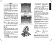
Page 3 LABEL 1 COPYRIGHT© 2005. All Rights Reserved. Please visit www.dewaltservicenet.com for DW713 Type 2 Description Qty Required TRUNNION 1 LOCKING PIN 1 O RING 1 BOLT 2 NUT 2 STUD 1 WASHER 1 BEVEL HANDLE 1 FENCE 1 LEFT FENCE 1 KNOB,LWR BEVEL 1 ROTARY TABLE 1 LOCK LEVER 1 PLATE 1 CLAMP PLATE 1 DETENT SPRING 1 POINTER 1 BEVEL POINTER 1 PLATE,KERF 1 SCREW 1 WASHER 2 NUT 1 BASE 1 DETENT...
Page 3 LABEL 1 COPYRIGHT© 2005. All Rights Reserved. Please visit www.dewaltservicenet.com for DW713 Type 2 Description Qty Required TRUNNION 1 LOCKING PIN 1 O RING 1 BOLT 2 NUT 2 STUD 1 WASHER 1 BEVEL HANDLE 1 FENCE 1 LEFT FENCE 1 KNOB,LWR BEVEL 1 ROTARY TABLE 1 LOCK LEVER 1 PLATE 1 CLAMP PLATE 1 DETENT SPRING 1 POINTER 1 BEVEL POINTER 1 PLATE,KERF 1 SCREW 1 WASHER 2 NUT 1 BASE 1 DETENT...

