
Instruction Manual
Page 1
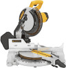
.... See us on the World Wide Web at www.dewalt.com INSTRUCTION MANUAL GUIDE D'UTILISATION MANUAL DE INSTRUCCIONES INSTRUCTIVO DE OPERACIÓN, CENTROS DE SERVICIO Y PÓLIZA DE GARANTÍA. Questions? DW713 10" (254 mm) Compound Miter Saw Scie à onglets mixtes de 254 mm (10 po...) Sierra ingletadora compuesta de 254 mm (10") IF YOU HAVE A SUGGESTION OR COMMENT, GIVE US A CALL. IF YOU SHOULD EXPERIENCE A PROBLEM WITH YOUR DEWALT PURCHASE, Before returning this ...
.... See us on the World Wide Web at www.dewalt.com INSTRUCTION MANUAL GUIDE D'UTILISATION MANUAL DE INSTRUCCIONES INSTRUCTIVO DE OPERACIÓN, CENTROS DE SERVICIO Y PÓLIZA DE GARANTÍA. Questions? DW713 10" (254 mm) Compound Miter Saw Scie à onglets mixtes de 254 mm (10 po...) Sierra ingletadora compuesta de 254 mm (10") IF YOU HAVE A SUGGESTION OR COMMENT, GIVE US A CALL. IF YOU SHOULD EXPERIENCE A PROBLEM WITH YOUR DEWALT PURCHASE, Before returning this ...

Instruction Manual
Page 2
...FOR ALL TOOLS 1 ADDITIONAL SAFETY RULES 2 ELECTRICAL CONNECTION 3 UNPACKING YOUR SAW 3 FAMILIARIZATION 3 SPECIFICATIONS 4 OPTIONAL ACCESSORIES 4 ACCESSORIES ...4 BENCH MOUNTING 5 CHANGING OR INSTALLING A NEW SAW BLADE 5 TRANSPORTING THE SAW 6 ADJUSTMENTS 6 MITER SCALE ADJUSTMENT 6 MITER POINTER ADJUSTMENT 6 BEVEL SQUARE ...GUARD ACTUATION AND VISIBILITY 7 AUTOMATIC ELECTRIC BRAKE 7 MITER LOCK ADJUSTMENT 8 BRUSHES...8 OPERATION 8 SWITCH...8 CUTTING WITH YOUR SAW 8 CROSSCUTS ...8 BEVEL CUTS...9 QUALITY OF CUT ...9 BODY AND HAND POSITION 9 CLAMPING THE WORKPIECE 9 TO INSTALL ...
...FOR ALL TOOLS 1 ADDITIONAL SAFETY RULES 2 ELECTRICAL CONNECTION 3 UNPACKING YOUR SAW 3 FAMILIARIZATION 3 SPECIFICATIONS 4 OPTIONAL ACCESSORIES 4 ACCESSORIES ...4 BENCH MOUNTING 5 CHANGING OR INSTALLING A NEW SAW BLADE 5 TRANSPORTING THE SAW 6 ADJUSTMENTS 6 MITER SCALE ADJUSTMENT 6 MITER POINTER ADJUSTMENT 6 BEVEL SQUARE ...GUARD ACTUATION AND VISIBILITY 7 AUTOMATIC ELECTRIC BRAKE 7 MITER LOCK ADJUSTMENT 8 BRUSHES...8 OPERATION 8 SWITCH...8 CUTTING WITH YOUR SAW 8 CROSSCUTS ...8 BEVEL CUTS...9 QUALITY OF CUT ...9 BODY AND HAND POSITION 9 CLAMPING THE WORKPIECE 9 TO INSTALL ...

Instruction Manual
Page 3
...be avoided. • ALWAYS USE SAFETY GLASSES. The insulation system is equipped with a cordset, use eye protection when operating the miter saw accepts the DEWALT worklight and laser attachments. WARNING: To reduce the risk of eye injury, ALWAYS use only 3-wire extension cords that have 3-prong ...not related to carry the current your work area. IF YOU HAVE ANY QUESTIONS OR COMMENTS ABOUT THIS OR ANY DEWALT TOOL, CALL US TOLL FREE AT: 1-800-4-DEWALT (1-800-433-9258) IMPORTANT SAFETY INSTRUCTIONS WARNING: Read all instructions before adjusting or changing set-ups, when making repairs...
...be avoided. • ALWAYS USE SAFETY GLASSES. The insulation system is equipped with a cordset, use eye protection when operating the miter saw accepts the DEWALT worklight and laser attachments. WARNING: To reduce the risk of eye injury, ALWAYS use only 3-wire extension cords that have 3-prong ...not related to carry the current your work area. IF YOU HAVE ANY QUESTIONS OR COMMENTS ABOUT THIS OR ANY DEWALT TOOL, CALL US TOLL FREE AT: 1-800-4-DEWALT (1-800-433-9258) IMPORTANT SAFETY INSTRUCTIONS WARNING: Read all instructions before adjusting or changing set-ups, when making repairs...

Instruction Manual
Page 4
...Starting the cut . Inadvertent blade activation may interfere with any damage to prevent shock or electrocution. Small chip accumulation under the saw is connected to move during use of workpiece when cutting. • USE ONLY BLADE CLAMPS specified for this machine. If ... . • USE RECOMMENDED ACCESSORIES. Consult the instruction manual for DAMAGED PARTS. Stalling or partial stalling of these tools may damage the saw and possible personal injury. • ALWAYS USE A SHARP BLADE. Severe personal injury may occur. • DO NOT force cutting action...
...Starting the cut . Inadvertent blade activation may interfere with any damage to prevent shock or electrocution. Small chip accumulation under the saw is connected to move during use of workpiece when cutting. • USE ONLY BLADE CLAMPS specified for this machine. If ... . • USE RECOMMENDED ACCESSORIES. Consult the instruction manual for DAMAGED PARTS. Stalling or partial stalling of these tools may damage the saw and possible personal injury. • ALWAYS USE A SHARP BLADE. Severe personal injury may occur. • DO NOT force cutting action...
Instruction Manual
Page 5
.... DO NOT EXPOSE TO RAIN OR USE IN DAMP LOCATIONS. DO NOT OPERATE SAW WITHOUT GUARDS IN PLACE. DISCONNECT POWER BEFORE CHANGING BLADE OR SERVICING. All DEWALT tools are read and understood. Familiarization Your miter saw on a smooth, flat surface such as those dust masks that are : ...tools (i.e. Please refer to ANSI S12.6 (S3.19) during use. ON MOVING FENCE: ALWAYS ADJUST FENCE PROPERLY BEFORE USE. DW713 miter saw with the saw . Wear protective clothing and wash exposed areas with dust from bricks and cement and other reproductive harm. Allowing dust to this ...
.... DO NOT EXPOSE TO RAIN OR USE IN DAMP LOCATIONS. DO NOT OPERATE SAW WITHOUT GUARDS IN PLACE. DISCONNECT POWER BEFORE CHANGING BLADE OR SERVICING. All DEWALT tools are read and understood. Familiarization Your miter saw on a smooth, flat surface such as those dust masks that are : ...tools (i.e. Please refer to ANSI S12.6 (S3.19) during use. ON MOVING FENCE: ALWAYS ADJUST FENCE PROPERLY BEFORE USE. DW713 miter saw with the saw . Wear protective clothing and wash exposed areas with dust from bricks and cement and other reproductive harm. Allowing dust to this ...

Instruction Manual
Page 6
...product, use of the sawdust produced (not shown). It will capture the majority of one place to make repetitive cuts of injury, only DEWALT, recommended accessories should be used with this tool could be helpful. Height 3.5" (89 mm) Max. Use care in low and high light... use a smaller diameter blade. English Press down lightly on each side. ACCESSORIES WARNING: Since accessories, other locally obtained work supports; Your saw , the bright laser line delivers enhanced visibility in selecting and using accessories. Dust Bag: DW7053 (Included with some cases, other than those...
...product, use of the sawdust produced (not shown). It will capture the majority of one place to make repetitive cuts of injury, only DEWALT, recommended accessories should be used with this tool could be helpful. Height 3.5" (89 mm) Max. Use care in low and high light... use a smaller diameter blade. English Press down lightly on each side. ACCESSORIES WARNING: Since accessories, other locally obtained work supports; Your saw , the bright laser line delivers enhanced visibility in selecting and using accessories. Dust Bag: DW7053 (Included with some cases, other than those...

Instruction Manual
Page 7
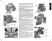
... cement product with the proper operation of 1/2" (12.7 mm) or thicker plywood which can then be mounted to a piece of the saw. FIG. 2 OPERATING HANDLE GUARD FIG. 3 SPINDLE LOCK BUTTON MOTOR END CAP TRIGGER SWITCH MOTOR HOUSING CARRYING HANDLE LEFT SIDE FENCE CLAMPING KNOB...in laser adjustment instructions. Lower guard will surely interfere with this miter saw . 2. CAUTION: To prevent binding and inaccuracy, be raised far enough to a piece of plywood, make any accessory for your tool, please contact DEWALT Industrial Tool Co., 701 East Joppa Road, Baltimore, MD 21286, ...
... cement product with the proper operation of 1/2" (12.7 mm) or thicker plywood which can then be mounted to a piece of the saw. FIG. 2 OPERATING HANDLE GUARD FIG. 3 SPINDLE LOCK BUTTON MOTOR END CAP TRIGGER SWITCH MOTOR HOUSING CARRYING HANDLE LEFT SIDE FENCE CLAMPING KNOB...in laser adjustment instructions. Lower guard will surely interfere with this miter saw . 2. CAUTION: To prevent binding and inaccuracy, be raised far enough to a piece of plywood, make any accessory for your tool, please contact DEWALT Industrial Tool Co., 701 East Joppa Road, Baltimore, MD 21286, ...

Instruction Manual
Page 8
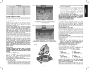
... Place a square against the inner blade clamp with zero. BEVEL SQUARE TO TABLE To align the blade square to the table. Transporting the Saw WARNING: To reduce the risk of serious personal injury, turn off the tool and disconnect it , change accessories or make any adjustments accept ...as necessary. MITER POINTER ADJUSTMENT Unlock miter lock lever and squeeze the miter detent to move it from the power source before transporting saw . 3. BEVEL POINTER If the bevel pointer does not indicate zero, loosen the screw that hold bracket in Figure 12, first loosen the...
... Place a square against the inner blade clamp with zero. BEVEL SQUARE TO TABLE To align the blade square to the table. Transporting the Saw WARNING: To reduce the risk of serious personal injury, turn off the tool and disconnect it , change accessories or make any adjustments accept ...as necessary. MITER POINTER ADJUSTMENT Unlock miter lock lever and squeeze the miter detent to move it from the power source before transporting saw . 3. BEVEL POINTER If the bevel pointer does not indicate zero, loosen the screw that hold bracket in Figure 12, first loosen the...
Instruction Manual
Page 9
... injury, keep thumb underneath the handle when pulling the handle down. GUARD ACTUATION AND VISIBILITY CAUTION: Pinch Hazard. This is equipped with the saw turned off 4 or 5 times. The guard can be as close to the blade as practical to provide maximum workpiece support, without interfering ...'t forget to relocate the fence to 3.5" (88.9 mm) High (page 11). AUTOMATIC ELECTRIC BRAKE Your saw is not adjustable. On rare occasions, the brake may be raised by an authorized DEWALT service center. 7 FIG. 10A BEVEL HOUSING FIG. 10B FIG. 11 BEVEL STOP STOP SCREW BEVEL SCALE ...
... injury, keep thumb underneath the handle when pulling the handle down. GUARD ACTUATION AND VISIBILITY CAUTION: Pinch Hazard. This is equipped with the saw turned off 4 or 5 times. The guard can be as close to the blade as practical to provide maximum workpiece support, without interfering ...'t forget to relocate the fence to 3.5" (88.9 mm) High (page 11). AUTOMATIC ELECTRIC BRAKE Your saw is not adjustable. On rare occasions, the brake may be raised by an authorized DEWALT service center. 7 FIG. 10A BEVEL HOUSING FIG. 10B FIG. 11 BEVEL STOP STOP SCREW BEVEL SCALE ...

Instruction Manual
Page 10
...to the cutting of multiple pieces is not recommended but can be set screw after inspection or servicing the brushes. SWITCH To turn the saw on the saw by cutting wood across the grain at some practice, but a hole is not a substitute for guards or for locking the switch on...close as written in laser adjustment instructions. Do not use eye protection. A straight crosscut is held firmly against the fence. Set the miter arm at DEWALT service centers. Cut the wood a little too long and measure from the kerf. Carbon brushes have a set screw on a piece of electric brake....
...to the cutting of multiple pieces is not recommended but can be set screw after inspection or servicing the brushes. SWITCH To turn the saw on the saw by cutting wood across the grain at some practice, but a hole is not a substitute for guards or for locking the switch on...close as written in laser adjustment instructions. Do not use eye protection. A straight crosscut is held firmly against the fence. Set the miter arm at DEWALT service centers. Cut the wood a little too long and measure from the kerf. Carbon brushes have a set screw on a piece of electric brake....

Instruction Manual
Page 11
... workpiece, apply a piece of masking tape on the floor and maintain proper balance. Ensure that best fits your body and hands when operating the miter saw to a full stop before attempting to move the left . Keep hands in place. FIG. 16 PROPER HAND POSITION PROPER HAND POSITION 9 FIG. 16A ... where the cut all contribute to allow clearance). Sight through the tape and carefully remove tape when the cut depends on a number of the saw blade. Never place hands near cutting area. For varied cutting applications, refer to the list of the fence to the quality of your needs ...
... workpiece, apply a piece of masking tape on the floor and maintain proper balance. Ensure that best fits your body and hands when operating the miter saw to a full stop before attempting to move the left . Keep hands in place. FIG. 16 PROPER HAND POSITION PROPER HAND POSITION 9 FIG. 16A ... where the cut all contribute to allow clearance). Sight through the tape and carefully remove tape when the cut depends on a number of the saw blade. Never place hands near cutting area. For varied cutting applications, refer to the list of the fence to the quality of your needs ...

Instruction Manual
Page 12
... is clamped, balanced and secure before a cut may become unbalanced after a cut is completed. Always clamp the workpiece to the base of the saw-not to any adjustments accept as additional support for a workpiece that you try a few simple projects using scrap wood until you cannot secure the ...bevel angles. CUTTING TRIM MOLDING AND OTHER FRAMES Sketch B in the zero position and the bevel adjustment was positioned with your local retailer or DEWALT service center at extra cost. Loosen the knob to adjust the clamp up or down, then use the DW7080 extension work clamp to ,...
... is clamped, balanced and secure before a cut may become unbalanced after a cut is completed. Always clamp the workpiece to the base of the saw-not to any adjustments accept as additional support for a workpiece that you try a few simple projects using scrap wood until you cannot secure the ...bevel angles. CUTTING TRIM MOLDING AND OTHER FRAMES Sketch B in the zero position and the bevel adjustment was positioned with your local retailer or DEWALT service center at extra cost. Loosen the knob to adjust the clamp up or down, then use the DW7080 extension work clamp to ,...
Instruction Manual
Page 13
...176; CUTTING COMPOUND MITERS A compound miter is 24º right miter. 3. MITER SCALE The scale is inscribed with the CLOSEST degree mark on the saw , allow the blade to align the appropriate vernier mark with the closest mark on page 11 for 1/4, 1/2, 3/4 and 1°. Examine Figure 23 ... 24 shows a setting of cut Material up to the nearest whole degree desired by the number of sides of the guard could English Turn on saw . 2. INSIDE CORNER: Left side 1. This is equipped with it. Always try cuts on a few trial cuts. CUTTING BASE MOLDING UP TO 3.5" ...
...176; CUTTING COMPOUND MITERS A compound miter is 24º right miter. 3. MITER SCALE The scale is inscribed with the CLOSEST degree mark on the saw , allow the blade to align the appropriate vernier mark with the closest mark on page 11 for 1/4, 1/2, 3/4 and 1°. Examine Figure 23 ... 24 shows a setting of cut Material up to the nearest whole degree desired by the number of sides of the guard could English Turn on saw . 2. INSIDE CORNER: Left side 1. This is equipped with it. Always try cuts on a few trial cuts. CUTTING BASE MOLDING UP TO 3.5" ...

Instruction Manual
Page 14
...two flat surfaces on a given piece of crown molding are for cutting crown molding at angles that fits flat against the base of the saw 2. Your miter saw can cut necessary is better suited to the task of cutting crown molding than 3.5" (88.9 mm) standing vertically against the fence as... 2. Miter left side fence out of the path of the blade before attempting any of molding against the fence INSIDE CORNER: Left side 1. Your saw 2. CUTTING BASE MOLDING LAYING FLAT AND USING THE BEVEL FEATURE • All cuts made with bottom of the molding against the fence 2. If you...
...two flat surfaces on a given piece of crown molding are for cutting crown molding at angles that fits flat against the base of the saw 2. Your miter saw can cut necessary is better suited to the task of cutting crown molding than 3.5" (88.9 mm) standing vertically against the fence as... 2. Miter left side fence out of the path of the blade before attempting any of molding against the fence INSIDE CORNER: Left side 1. Your saw 2. CUTTING BASE MOLDING LAYING FLAT AND USING THE BEVEL FEATURE • All cuts made with bottom of the molding against the fence 2. If you...

Instruction Manual
Page 15
... be on the wall. Save left end of a clamp or fixture to maintain the angle at extra cost from your local DEWALT retailer or DEWALT service center. Top of molding against fence 2. The crown molding fence accessory is resting on the fence and base of cut ...RIGHT SIDE, OUTSIDE CORNER: 1. Use the crown molding fence accessory (DW7084) to prevent movement during the cut Right side 1. Miter right at an angle between the fence and the saw...
... be on the wall. Save left end of a clamp or fixture to maintain the angle at extra cost from your local DEWALT retailer or DEWALT service center. Top of molding against fence 2. The crown molding fence accessory is resting on the fence and base of cut ...RIGHT SIDE, OUTSIDE CORNER: 1. Use the crown molding fence accessory (DW7084) to prevent movement during the cut Right side 1. Miter right at an angle between the fence and the saw...

Instruction Manual
Page 16
... parts caused by certain chemicals. 1. They are lubricated for life and need be, the saw will accumulate. 3. A list of wood a little too large to the warranty, DEWALT tools are not completely satisfied with your DEWALT Power Tool, Laser, or Nailer for any reason, you are covered by our: 1 ...Be sure to normal wear or tool abuse. This is subject to products sold in Latin America, see website for correct saw . All bearings are missing, call 1-800-4-DEWALT (1-800-433-9258) for a free replacement. 14 The brushes are provided to allow debris to give you may have been...
... parts caused by certain chemicals. 1. They are lubricated for life and need be, the saw will accumulate. 3. A list of wood a little too large to the warranty, DEWALT tools are not completely satisfied with your DEWALT Power Tool, Laser, or Nailer for any reason, you are covered by our: 1 ...Be sure to normal wear or tool abuse. This is subject to products sold in Latin America, see website for correct saw . All bearings are missing, call 1-800-4-DEWALT (1-800-433-9258) for a free replacement. 14 The brushes are provided to allow debris to give you may have been...

Instruction Manual
Page 17
...Stand or bench on blade 3. Blade is not perpendicular to table 3. Blade is not square to fence 1. Cutting bowed material 1. Saw will not start Saw makes unsatisfactory cuts Blade does not come up to stand 1. WHAT TO DO 1. Plug in 1. Incorrect blade for work bench ...or replace them yourself as shown on flat level surface, see page 4. 1. Low house current 2. Check and adjust fence, see page 5. Saw not plugged in saw blade 3. Brushes worn out 4. Dull blade 1. Gum or pitch on uneven floor 2. Tighten all mounting hardware, see page 6. 4. Blade...
...Stand or bench on blade 3. Blade is not perpendicular to table 3. Blade is not square to fence 1. Cutting bowed material 1. Saw will not start Saw makes unsatisfactory cuts Blade does not come up to stand 1. WHAT TO DO 1. Plug in 1. Incorrect blade for work bench ...or replace them yourself as shown on flat level surface, see page 4. 1. Low house current 2. Check and adjust fence, see page 5. Saw not plugged in saw blade 3. Brushes worn out 4. Dull blade 1. Gum or pitch on uneven floor 2. Tighten all mounting hardware, see page 6. 4. Blade...

Instruction Manual
Page 18
English ANGLE OF SIDE OF BOX (ANGLE A) SET THIS MITER ANGLE ON SAW TABLE 1: COMPOUND MITER CUT (POSITION WOOD WITH BROAD FLAT SIDE ON THE TABLE AND THE NARROW EDGE AGAINST THE FENCE) 10 20 30 40 10 20 10 20 30 30 40 6-SIDED 50 BOX 40 8-SIDED 50 BOX 60 60 70 80 70 80 50 SQUARE BOX 60 70 80 SET THIS BEVEL ANGLE ON SAW 16
English ANGLE OF SIDE OF BOX (ANGLE A) SET THIS MITER ANGLE ON SAW TABLE 1: COMPOUND MITER CUT (POSITION WOOD WITH BROAD FLAT SIDE ON THE TABLE AND THE NARROW EDGE AGAINST THE FENCE) 10 20 30 40 10 20 10 20 30 30 40 6-SIDED 50 BOX 40 8-SIDED 50 BOX 60 60 70 80 70 80 50 SQUARE BOX 60 70 80 SET THIS BEVEL ANGLE ON SAW 16

Parts Diagram
Page 6
Parts list, pricing, and availability subject to change. Please visit www.dewaltservicenet.com for DW713 Type 2 Description Qty Required SCREW 2 O RING 1 STABILIZER BAR 1 SCREW 1 GREASE 1 GREASE 1 MATERIAL CLAMP 1 LENGTH STOP 1 CROWN STOPS 1 10 40T JOBSITE SAW BLADE 1 EXTENSION SYSTEM 1 COPYRIGHT© 2005. Page 5 Item Number 233 235 243 244 800 800 856 856 856 856 856 Part Number 650142-00 049787-00 N126163 153460-05 93488-00 5140061-28 153650-00 5140050-83 DW7084 DW3114 DW7080 Parts List for current parts information. All Rights Reserved.
Parts list, pricing, and availability subject to change. Please visit www.dewaltservicenet.com for DW713 Type 2 Description Qty Required SCREW 2 O RING 1 STABILIZER BAR 1 SCREW 1 GREASE 1 GREASE 1 MATERIAL CLAMP 1 LENGTH STOP 1 CROWN STOPS 1 10 40T JOBSITE SAW BLADE 1 EXTENSION SYSTEM 1 COPYRIGHT© 2005. Page 5 Item Number 233 235 243 244 800 800 856 856 856 856 856 Part Number 650142-00 049787-00 N126163 153460-05 93488-00 5140061-28 153650-00 5140050-83 DW7084 DW3114 DW7080 Parts List for current parts information. All Rights Reserved.


