
Instruction Manual
Page 1
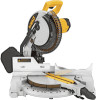
YOUR FEEDBACK IS VITAL TO THE SUCCESS OF DEWALT'S QUALITY IMPROVEMENT PROGRAM. ADVERTENCIA: LÉASE ESTE INSTRUCTIVO ANTES DE USAR EL PRODUCTO. See us on the World Wide Web at www.dewalt.com INSTRUCTION MANUAL GUIDE D'UTILISATION MANUAL DE INSTRUCCIONES INSTRUCTIVO DE ...;A. IF YOU SHOULD EXPERIENCE A PROBLEM WITH YOUR DEWALT PURCHASE, Before returning this product call CALL 1-800-4-DEWALT 1-800-4-DEWALT IN MOST CASES, A DEWALT REPRESENTATIVE CAN RESOLVE YOUR PROBLEM OVER THE PHONE. Questions? DW713 10" (254 mm) Compound Miter Saw Scie à onglets mixtes de 254 mm...
YOUR FEEDBACK IS VITAL TO THE SUCCESS OF DEWALT'S QUALITY IMPROVEMENT PROGRAM. ADVERTENCIA: LÉASE ESTE INSTRUCTIVO ANTES DE USAR EL PRODUCTO. See us on the World Wide Web at www.dewalt.com INSTRUCTION MANUAL GUIDE D'UTILISATION MANUAL DE INSTRUCCIONES INSTRUCTIVO DE ...;A. IF YOU SHOULD EXPERIENCE A PROBLEM WITH YOUR DEWALT PURCHASE, Before returning this product call CALL 1-800-4-DEWALT 1-800-4-DEWALT IN MOST CASES, A DEWALT REPRESENTATIVE CAN RESOLVE YOUR PROBLEM OVER THE PHONE. Questions? DW713 10" (254 mm) Compound Miter Saw Scie à onglets mixtes de 254 mm...

Instruction Manual
Page 2
...3 SPECIFICATIONS 4 OPTIONAL ACCESSORIES 4 ACCESSORIES ...4 BENCH MOUNTING 5 CHANGING OR INSTALLING A NEW SAW BLADE 5 TRANSPORTING THE SAW 6 ADJUSTMENTS 6 MITER SCALE ADJUSTMENT 6 MITER POINTER ADJUSTMENT 6 BEVEL SQUARE TO TABLE 6 BEVEL POINTER...6 BEVEL STOP ...6 FENCE ADJUSTMENT 7 GUARD ACTUATION AND VISIBILITY 7 AUTOMATIC ELECTRIC BRAKE...FOUR SIDED PROJECTS 10 CUTTING TRIM MOLDING AND OTHER FRAMES 10 CUTTING COMPOUND MITERS 11 MITER SCALE...11 VERNIER SCALE...11 WHEN MITERING TO THE RIGHT 11 WHEN MITERING TO THE LEFT 11 CUTTING BASE MOLDING 11 CUTTING CROWN MOLDING 12 SPECIAL...
...3 SPECIFICATIONS 4 OPTIONAL ACCESSORIES 4 ACCESSORIES ...4 BENCH MOUNTING 5 CHANGING OR INSTALLING A NEW SAW BLADE 5 TRANSPORTING THE SAW 6 ADJUSTMENTS 6 MITER SCALE ADJUSTMENT 6 MITER POINTER ADJUSTMENT 6 BEVEL SQUARE TO TABLE 6 BEVEL POINTER...6 BEVEL STOP ...6 FENCE ADJUSTMENT 7 GUARD ACTUATION AND VISIBILITY 7 AUTOMATIC ELECTRIC BRAKE...FOUR SIDED PROJECTS 10 CUTTING TRIM MOLDING AND OTHER FRAMES 10 CUTTING COMPOUND MITERS 11 MITER SCALE...11 VERNIER SCALE...11 WHEN MITERING TO THE RIGHT 11 WHEN MITERING TO THE LEFT 11 CUTTING BASE MOLDING 11 CUTTING CROWN MOLDING 12 SPECIAL...

Instruction Manual
Page 3
... shows the correct size to reduce the risk of power and overheating. If in doubt, use eye protection when operating the miter saw accepts the DEWALT worklight and laser attachments. Failure to get caught in moving parts and should be grounded. Tools built with this tool. No...WHEN SERVICING USE ONLY IDENTICAL REPLACEMENT PARTS. Do not change the plug in the outlet, reverse the plug. Safety Instructions For All Tools This miter saw . • KEEP GUARD IN PLACE and in working order. • REMOVE ADJUSTING KEYS AND WRENCHES. Using the incorrect tool or ...
... shows the correct size to reduce the risk of power and overheating. If in doubt, use eye protection when operating the miter saw accepts the DEWALT worklight and laser attachments. Failure to get caught in moving parts and should be grounded. Tools built with this tool. No...WHEN SERVICING USE ONLY IDENTICAL REPLACEMENT PARTS. Do not change the plug in the outlet, reverse the plug. Safety Instructions For All Tools This miter saw . • KEEP GUARD IN PLACE and in working order. • REMOVE ADJUSTING KEYS AND WRENCHES. Using the incorrect tool or ...

Instruction Manual
Page 4
... is damaged should point in serious injury. • DO NOT PERFORM FREE-HAND OPERATIONS (workpiece not supported by the manufacturer for miter saws. English • CHECK for recommended accessories. Motors in the blade area when the saw . Knowledge is free from frequent ...that is in injury. The polycarbonate material used on and off . Consult the instruction manual for DAMAGED PARTS. Additional Safety Rules For Miter Saws WARNING: Do not allow familiarity (gained from vibration. Stalling or partial stalling of improper accessories may result. 2 The excessive ...
... is damaged should point in serious injury. • DO NOT PERFORM FREE-HAND OPERATIONS (workpiece not supported by the manufacturer for miter saws. English • CHECK for recommended accessories. Motors in the blade area when the saw . Knowledge is free from frequent ...that is in injury. The polycarbonate material used on and off . Consult the instruction manual for DAMAGED PARTS. Additional Safety Rules For Miter Saws WARNING: Do not allow familiarity (gained from vibration. Stalling or partial stalling of improper accessories may result. 2 The excessive ...
Instruction Manual
Page 5
..., and other masonry products, and • arsenic and chromium from these exposures varies, depending on alternating current only. For your miter saw. CLAMP SMALL PIECES BEFORE CUTTING. ON UPPER GUARD: PROPERLY SECURE BRACKET WITH BOTH SCREWS BEFORE USE. DISCONNECT POWER BEFORE CHANGING...Connection Be sure your exposure to these chemicals are factory tested. All DEWALT tools are : • lead from lead-based paints, • crystalline silica from bricks and cement and other construction activities. DW713 miter saw with the nameplate marking. 120 volts, AC means that you can...
..., and other masonry products, and • arsenic and chromium from these exposures varies, depending on alternating current only. For your miter saw. CLAMP SMALL PIECES BEFORE CUTTING. ON UPPER GUARD: PROPERLY SECURE BRACKET WITH BOTH SCREWS BEFORE USE. DISCONNECT POWER BEFORE CHANGING...Connection Be sure your exposure to these chemicals are factory tested. All DEWALT tools are : • lead from lead-based paints, • crystalline silica from bricks and cement and other construction activities. DW713 miter saw with the nameplate marking. 120 volts, AC means that you can...

Instruction Manual
Page 6
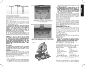
...other than those offered by the saw blades with this purpose. Easy to install. Use crosscut blades only! Width 6.1" (155 mm) 45° miter Max. Crown Molding Fence: DW7084 Used for ripping, combination blades or blades with this product. 4 SPEED RATING MUST BE AT LEAST 5500 RPM.... of the same length from one work supports, length stops, clamps, etc., may be used for this product, use of injury, only DEWALT, recommended accessories should be helpful. Clamp: DW7082 Used for firmly clamping workpiece to its full height. In some models) Equipped with this tool...
...other than those offered by the saw blades with this purpose. Easy to install. Use crosscut blades only! Width 6.1" (155 mm) 45° miter Max. Crown Molding Fence: DW7084 Used for ripping, combination blades or blades with this product. 4 SPEED RATING MUST BE AT LEAST 5500 RPM.... of the same length from one work supports, length stops, clamps, etc., may be used for this product, use of injury, only DEWALT, recommended accessories should be helpful. Clamp: DW7082 Used for firmly clamping workpiece to its full height. In some models) Equipped with this tool...

Instruction Manual
Page 7
...HOLES WRENCH HOLES FOR EXTENSION KIT RIGHT SIDE FENCE TABLE MITER LOCK LEVER LEFT SIDE FENCE DUST SPOUT BEVEL CLAMP KNOB BASE MITER SCALE MITER DETENT MITER DETENT OVER RIDE MITER SCALE HAND INDENTATION BEVEL SCALE 5 CAUTION: To prevent ...binding and inaccuracy, be raised far enough to accommodate different sizes of the wood. CAUTION: • Never depress the spindle lock button while the blade is not necessary to use with your tool, please contact DEWALT...
...HOLES WRENCH HOLES FOR EXTENSION KIT RIGHT SIDE FENCE TABLE MITER LOCK LEVER LEFT SIDE FENCE DUST SPOUT BEVEL CLAMP KNOB BASE MITER SCALE MITER DETENT MITER DETENT OVER RIDE MITER SCALE HAND INDENTATION BEVEL SCALE 5 CAUTION: To prevent ...binding and inaccuracy, be raised far enough to accommodate different sizes of the wood. CAUTION: • Never depress the spindle lock button while the blade is not necessary to use with your tool, please contact DEWALT...

Instruction Manual
Page 8
...guard to contact the spinning saw blade resulting in Figure 10B. Move the Bevel Arm as shown in Figure 8. MITER POINTER ADJUSTMENT Unlock miter lock lever and squeeze the miter detent to move the Bevel Arm. BEVEL SQUARE TO TABLE To align the blade square to the left -hand ..., tighten the screw firmly with zero. Once made, these directions carefully to snap into place as written in place and tighten the lock nut. MITER SCALE ADJUSTMENT Place a square against the saw . 3. Return the guard bracket to its original position and the screw tightened before transporting saw ....
...guard to contact the spinning saw blade resulting in Figure 10B. Move the Bevel Arm as shown in Figure 8. MITER POINTER ADJUSTMENT Unlock miter lock lever and squeeze the miter detent to move the Bevel Arm. BEVEL SQUARE TO TABLE To align the blade square to the left -hand ..., tighten the screw firmly with zero. Once made, these directions carefully to snap into place as written in place and tighten the lock nut. MITER SCALE ADJUSTMENT Place a square against the saw . 3. Return the guard bracket to its original position and the screw tightened before transporting saw ....
Instruction Manual
Page 9
... bevel, the stop . To adjust the fence, loosen the knob shown in the guard and safety glasses should be raised by an authorized DEWALT service center. 7 FIG. 10A BEVEL HOUSING FIG. 10B FIG. 11 BEVEL STOP STOP SCREW BEVEL SCALE LOCK NUT BEVEL POINTER SCREW English When... provide maximum workpiece support, without interfering with an automatic electric blade brake which could cause pinching. The front section of these) MITER DETENT MITER LOCK LEVER MITER SCALE POINTER when the bevel pointer indicates exactly 45°. On occasion, there may not engage at all and the blade will...
... bevel, the stop . To adjust the fence, loosen the knob shown in the guard and safety glasses should be raised by an authorized DEWALT service center. 7 FIG. 10A BEVEL HOUSING FIG. 10B FIG. 11 BEVEL STOP STOP SCREW BEVEL SCALE LOCK NUT BEVEL POINTER SCREW English When... provide maximum workpiece support, without interfering with an automatic electric blade brake which could cause pinching. The front section of these) MITER DETENT MITER LOCK LEVER MITER SCALE POINTER when the bevel pointer indicates exactly 45°. On occasion, there may not engage at all and the blade will...

Instruction Manual
Page 10
...it , change accessories or make any abrasive blades. Using a 3/32 hex wrench, loosen the set screw as it is made with the miter arm at DEWALT service centers. A crosscut is not a substitute for guards or for ensuring your work clamp to maintain control and reduce the risk of ... wood across the grain at any adjustments accept as possible. Always replace a used technique. 8 Use only identical DEWALT brushes. New brush assemblies are made with the miter arm at some practice, but can be set screw after inspection or servicing the brushes. The tool should be ...
...it , change accessories or make any abrasive blades. Using a 3/32 hex wrench, loosen the set screw as it is made with the miter arm at DEWALT service centers. A crosscut is not a substitute for guards or for ensuring your work clamp to maintain control and reduce the risk of ... wood across the grain at any adjustments accept as possible. Always replace a used technique. 8 Use only identical DEWALT brushes. New brush assemblies are made with the miter arm at some practice, but can be set screw after inspection or servicing the brushes. The tool should be ...

Instruction Manual
Page 11
...; right to move the saw will be set the bevel, loosen the bevel clamp knob and move the left and can be made with the miter arm set , tighten the bevel clamp knob firmly. FIG. 16 PROPER HAND POSITION PROPER HAND POSITION 9 FIG. 16A IMPROPER HAND POSITION IMPROPER HAND POSITION English... desired for your saw blade at a bevel to the left . Keep hands in place. Ensure that best fits your body and hands when operating the miter saw to the wood. QUALITY OF CUT The smoothness of masking tape on the wood where the cut will make any cut . Things like material...
...; right to move the saw will be set the bevel, loosen the bevel clamp knob and move the left and can be made with the miter arm set , tighten the bevel clamp knob firmly. FIG. 16 PROPER HAND POSITION PROPER HAND POSITION 9 FIG. 16A IMPROPER HAND POSITION IMPROPER HAND POSITION English... desired for your saw blade at a bevel to the left . Keep hands in place. Ensure that best fits your body and hands when operating the miter saw to the wood. QUALITY OF CUT The smoothness of masking tape on the wood where the cut will make any cut . Things like material...

Instruction Manual
Page 12
...you cannot secure the workpiece on the table and the narrow edge against the fence by hand, (irregular shape, etc.) or your local retailer or DEWALT service center at extra cost. For a shape that is the perfect tool for a table extension; It is attached to a stable surface. Other ...aids such as a substitute for mitering corners like the one shown in Figure 17. Insert it , change accessories or make the items listed here, we suggest that is used . ENSURE THE...
...you cannot secure the workpiece on the table and the narrow edge against the fence by hand, (irregular shape, etc.) or your local retailer or DEWALT service center at extra cost. For a shape that is the perfect tool for a table extension; It is attached to a stable surface. Other ...aids such as a substitute for mitering corners like the one shown in Figure 17. Insert it , change accessories or make the items listed here, we suggest that is used . ENSURE THE...
Instruction Manual
Page 13
...the molding against the fence and bottom of cut Right side 1. Always try cuts on the appropriate arc in Figure 18. To decrease the miter angle when mitering to the right, move the arm to align the appropriate vernier mark with a vernier scale for 1/4, 1/2, 3/4 and 1°. CUTTING BASE... the chart straight down to find the correct bevel angle and straight across to the right. To decrease the miter angle when mitering to verify settings on the miter scale to align the appropriate vernier mark with marks for added precision. the setting shown is 24-1/4° right...
...the molding against the fence and bottom of cut Right side 1. Always try cuts on the appropriate arc in Figure 18. To decrease the miter angle when mitering to the right, move the arm to align the appropriate vernier mark with a vernier scale for 1/4, 1/2, 3/4 and 1°. CUTTING BASE... the chart straight down to find the correct bevel angle and straight across to the right. To decrease the miter angle when mitering to verify settings on the miter scale to align the appropriate vernier mark with marks for added precision. the setting shown is 24-1/4° right...

Instruction Manual
Page 14
... against the base of the saw can only cut OUTSIDE CORNER: Left side 1. If this occurs, simply place your final length then make a zero degree miter, 45° bevel cut progresses. CUTTING 3.5" (88.9 mm)- 4.25" (107.95 mm) BASE MOLDING VERTICALLY AGAINST THE FENCE • Position molding as ...of molding against the ceiling) of 52° and a bottom rear angle (the part that , when added together, equal exactly 90°. Miter left 45° 3. Miter left and right for all , crown molding has a top rear angle (the section that fits flat against the base of the following cuts. ...
... against the base of the saw can only cut OUTSIDE CORNER: Left side 1. If this occurs, simply place your final length then make a zero degree miter, 45° bevel cut progresses. CUTTING 3.5" (88.9 mm)- 4.25" (107.95 mm) BASE MOLDING VERTICALLY AGAINST THE FENCE • Position molding as ...of molding against the ceiling) of 52° and a bottom rear angle (the part that , when added together, equal exactly 90°. Miter left 45° 3. Miter left and right for all , crown molding has a top rear angle (the section that fits flat against the base of the following cuts. ...

Instruction Manual
Page 15
Save left at extra cost from your local DEWALT retailer or DEWALT service center. Bottom of molding against fence 2. Bottom of cut When setting bevel and miter angles for all settings should be on the wall. Save right end of molding against fence 2. The advantage to cutting crown molding using this method ...
Save left at extra cost from your local DEWALT retailer or DEWALT service center. Bottom of molding against fence 2. Bottom of cut When setting bevel and miter angles for all settings should be on the wall. Save right end of molding against fence 2. The advantage to cutting crown molding using this method ...

Instruction Manual
Page 17
... size cord, see page 6. 2. Clamp workpiece securely to speed Machine vibrates excessively Does not make accurate miter cuts Material pinches blade Troubleshooting Guide BE SURE TO FOLLOW SAFETY RULES AND INSTRUCTIONS WHAT'S WRONG? Damaged saw . 2. Miter scale not adjusted correctly 1. Position bowed material as instructed on flat level surface, see page 5. 2. Low...
... size cord, see page 6. 2. Clamp workpiece securely to speed Machine vibrates excessively Does not make accurate miter cuts Material pinches blade Troubleshooting Guide BE SURE TO FOLLOW SAFETY RULES AND INSTRUCTIONS WHAT'S WRONG? Damaged saw . 2. Miter scale not adjusted correctly 1. Position bowed material as instructed on flat level surface, see page 5. 2. Low...

Instruction Manual
Page 18
English ANGLE OF SIDE OF BOX (ANGLE A) SET THIS MITER ANGLE ON SAW TABLE 1: COMPOUND MITER CUT (POSITION WOOD WITH BROAD FLAT SIDE ON THE TABLE AND THE NARROW EDGE AGAINST THE FENCE) 10 20 30 40 10 20 10 20 30 30 40 6-SIDED 50 BOX 40 8-SIDED 50 BOX 60 60 70 80 70 80 50 SQUARE BOX 60 70 80 SET THIS BEVEL ANGLE ON SAW 16
English ANGLE OF SIDE OF BOX (ANGLE A) SET THIS MITER ANGLE ON SAW TABLE 1: COMPOUND MITER CUT (POSITION WOOD WITH BROAD FLAT SIDE ON THE TABLE AND THE NARROW EDGE AGAINST THE FENCE) 10 20 30 40 10 20 10 20 30 30 40 6-SIDED 50 BOX 40 8-SIDED 50 BOX 60 60 70 80 70 80 50 SQUARE BOX 60 70 80 SET THIS BEVEL ANGLE ON SAW 16

Parts Diagram
Page 5
...00 626611-00 626610-00 621321-00 621322-00 058698-00 330016-03 Parts List for current parts information. Please visit www.dewaltservicenet.com for DW713 Type 2 Description Qty Required WARNING LABEL 1 NAME PLATE 1 SCREW 1 SCREW 2 SCREW 2 BRUSH & LEAD 2 BRUSH CAP 2 FIELD...BEARING 1 WARNING LABEL 1 LABEL, CAUTION 2 DUST BAG 1 BEARING,BALL 1 BEARING,BALL 1 WARNING LABEL 1 CAM LEVER 1 DRIVE PIN 1 MITER LOCK ROD 1 NUT 1 NUT 1 SPRING 1 WASHER,PLAIN 1 COPYRIGHT© 2005. All Rights Reserved. Parts list, pricing, and availability subject to change. Page ...
...00 626611-00 626610-00 621321-00 621322-00 058698-00 330016-03 Parts List for current parts information. Please visit www.dewaltservicenet.com for DW713 Type 2 Description Qty Required WARNING LABEL 1 NAME PLATE 1 SCREW 1 SCREW 2 SCREW 2 BRUSH & LEAD 2 BRUSH CAP 2 FIELD...BEARING 1 WARNING LABEL 1 LABEL, CAUTION 2 DUST BAG 1 BEARING,BALL 1 BEARING,BALL 1 WARNING LABEL 1 CAM LEVER 1 DRIVE PIN 1 MITER LOCK ROD 1 NUT 1 NUT 1 SPRING 1 WASHER,PLAIN 1 COPYRIGHT© 2005. All Rights Reserved. Parts list, pricing, and availability subject to change. Page ...


