
Instruction Manual
Page 1
... trigger lock button (O) is in accordance with care. Follow instructions in the OPERATION: FIXED BASE section of this manual. tive harm. Some examples of drugs, alcohol, or medication. WARNING: Use of this tool does not operate, check the power supply. Always use tool if switch does not turn the nut (Y) in the socket. SET-UP: FIXED BASE Motor Quick Release (Fig. 2) CAUTION: Turn the router off . Inserting the Motor into the base by turning the depth adjustment ring. Open the locking lever...
... trigger lock button (O) is in accordance with care. Follow instructions in the OPERATION: FIXED BASE section of this manual. tive harm. Some examples of drugs, alcohol, or medication. WARNING: Use of this tool does not operate, check the power supply. Always use tool if switch does not turn the nut (Y) in the socket. SET-UP: FIXED BASE Motor Quick Release (Fig. 2) CAUTION: Turn the router off . Inserting the Motor into the base by turning the depth adjustment ring. Open the locking lever...

Instruction Manual
Page 2
... the work . Bit Installation and Removal (Fig. 6) CAUTION: Turn the router off and disconnect it from the power supply. Continue turning the collet nut counterclockwise. To change , or replace the subbase, a centering tool is running. Open the locking lever (D) and turn the nut (Y) in the base when the locking lever is to follow these steps: 1. Using a Parallel Fence A parallel fence (DW6913) is adjustable. Using the wrench(es) provided, turn off . At this tool could create an electrical shock...
... the work . Bit Installation and Removal (Fig. 6) CAUTION: Turn the router off and disconnect it from the power supply. Continue turning the collet nut counterclockwise. To change , or replace the subbase, a centering tool is running. Open the locking lever (D) and turn the nut (Y) in the base when the locking lever is to follow these steps: 1. Using a Parallel Fence A parallel fence (DW6913) is adjustable. Using the wrench(es) provided, turn off . At this tool could create an electrical shock...
Parts Diagram
Page 2
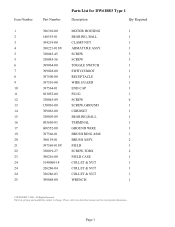
... www.dewaltservicenet.com for DW618B3 Type 1 Description Qty Required 396310-00 MOTOR HOUSING 1 146555-01 BEARING, BALL 1 394219-00 CLAMP NUT 1 398221-01SV ARMATURE ASSY. 1 330045-45 SCREW 3 330045-56 SCREW 3 399064-00 TOGGLE SWITCH 1 399028-00 SWITCH BOOT 1 397500-00 RECEPTACLE 1 397501-00 WIRE GUARD 1 397564-01 END CAP 1 033055-00 PLUG 1 330045-09 SCREW 4 150036-00 SCREW,GROUND 1 399063-00 CORDSET...
... www.dewaltservicenet.com for DW618B3 Type 1 Description Qty Required 396310-00 MOTOR HOUSING 1 146555-01 BEARING, BALL 1 394219-00 CLAMP NUT 1 398221-01SV ARMATURE ASSY. 1 330045-45 SCREW 3 330045-56 SCREW 3 399064-00 TOGGLE SWITCH 1 399028-00 SWITCH BOOT 1 397500-00 RECEPTACLE 1 397501-00 WIRE GUARD 1 397564-01 END CAP 1 033055-00 PLUG 1 330045-09 SCREW 4 150036-00 SCREW,GROUND 1 399063-00 CORDSET...
Parts Diagram
Page 3
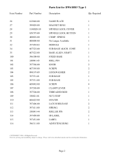
... 397451-00 396311-00 Parts List for current parts information. Page 2 SHAFT 1 FIXED BASE 1 ROLL PIN 3 KNOB 2 SCREW 2 LOCKWASHER 2 SUB BASE 1 SUB BASE 1 SCREW 4 CLAMP LEVER 1 THREADED ROD 1 NUT,STOP 1 SPACER 1 LATCH RELEASE 2 SPRING 2 ROLLER PIN 2 ID LABEL 1 LABEL 1 ADJUSTING RING 1 COPYRIGHT© 2005. Parts list, pricing, and availability subject to change. Please visit www.dewaltservicenet.com for DW618B3 Type 1 Description Qty Required NAME PLATE 1 MAGNET RING 1 SPINDLE LOCK COVER 1 SPINDLE LOCK BUTTON 1 COMP. SPRING 1 No Longer...
... 397451-00 396311-00 Parts List for current parts information. Page 2 SHAFT 1 FIXED BASE 1 ROLL PIN 3 KNOB 2 SCREW 2 LOCKWASHER 2 SUB BASE 1 SUB BASE 1 SCREW 4 CLAMP LEVER 1 THREADED ROD 1 NUT,STOP 1 SPACER 1 LATCH RELEASE 2 SPRING 2 ROLLER PIN 2 ID LABEL 1 LABEL 1 ADJUSTING RING 1 COPYRIGHT© 2005. Parts list, pricing, and availability subject to change. Please visit www.dewaltservicenet.com for DW618B3 Type 1 Description Qty Required NAME PLATE 1 MAGNET RING 1 SPINDLE LOCK COVER 1 SPINDLE LOCK BUTTON 1 COMP. SPRING 1 No Longer...
Parts Diagram
Page 4
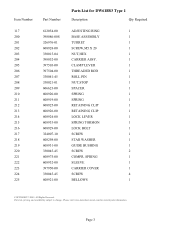
Parts list, pricing, and availability subject to change. Please visit www.dewaltservicenet.com for DW618B3 Type 1 Description Qty Required ADJUSTING RING 1 BASE ASSEMBLY 1 TURRET 1 SCREW,M5 X 20 1 NUT,HEX 1 CARRIER ASSY. 1 CLAMP LEVER 1 THREADED ROD 1 ROLL PIN 1 NUT,STOP 1 SPACER 1 SPRING 1 SPRING 1 RETAINING CLIP 1 RETAINING CLIP 1 LOCK LEVER 1 SPRING TORSION 1 LOCK BOLT 1 SCREW 1 STAR WASHER 1 GUIDE BUSHING 1 SCREW 2 COMPR. Page 3 SPRING 1 SLEEVE 1 CARRIER COVER 1 SCREW 4 BELLOWS 1 COPYRIGHT© 2005. All Rights Reserved. ...
Parts list, pricing, and availability subject to change. Please visit www.dewaltservicenet.com for DW618B3 Type 1 Description Qty Required ADJUSTING RING 1 BASE ASSEMBLY 1 TURRET 1 SCREW,M5 X 20 1 NUT,HEX 1 CARRIER ASSY. 1 CLAMP LEVER 1 THREADED ROD 1 ROLL PIN 1 NUT,STOP 1 SPACER 1 SPRING 1 SPRING 1 RETAINING CLIP 1 RETAINING CLIP 1 LOCK LEVER 1 SPRING TORSION 1 LOCK BOLT 1 SCREW 1 STAR WASHER 1 GUIDE BUSHING 1 SCREW 2 COMPR. Page 3 SPRING 1 SLEEVE 1 CARRIER COVER 1 SCREW 4 BELLOWS 1 COPYRIGHT© 2005. All Rights Reserved. ...
Parts Diagram
Page 5
Parts list, pricing, and availability subject to change. All Rights Reserved. Page 4 SPRING 2 SCREW 1 KNOB 2 SCREW 2 LOCKWASHER 2 DUST SHROUD 1 SUB BASE 1 SCREW 3 DEPTH SCALE 1 IDENT LABEL 1 LABEL 1 VACUUM ADAPTER 1 DETENT 1 SPRING WASHER 1 SCREW 1 SPRING,EXT. 1 SCREW M4X20 T20 1 WASHER 1 SPACER 1 SPRING 1 BALL 1 BASE 1 ROLL PIN 3 COPYRIGHT© 2005. Item Number 226 227 228 229 230 231 232 233 234 235 236 237 238 239 240 241 242 243 244 245 250 251 252...
Parts list, pricing, and availability subject to change. All Rights Reserved. Page 4 SPRING 2 SCREW 1 KNOB 2 SCREW 2 LOCKWASHER 2 DUST SHROUD 1 SUB BASE 1 SCREW 3 DEPTH SCALE 1 IDENT LABEL 1 LABEL 1 VACUUM ADAPTER 1 DETENT 1 SPRING WASHER 1 SCREW 1 SPRING,EXT. 1 SCREW M4X20 T20 1 WASHER 1 SPACER 1 SPRING 1 BALL 1 BASE 1 ROLL PIN 3 COPYRIGHT© 2005. Item Number 226 227 228 229 230 231 232 233 234 235 236 237 238 239 240 241 242 243 244 245 250 251 252...
Parts Diagram
Page 6
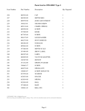
...Please visit www.dewaltservicenet.com for DW618B3 Type 1 Description Qty Required NUT,STOP 1 SPACER 1 SUB BASE 1 SUB BASE 1 SCREW 4 LATCH RELEASE 2 SPRING 2 ROLLER PIN 2 CLAMP LEVER 1 THREADED ROD 1 ID LABEL 1 KNOB 1 SCREW 1 LOCKWASHER 1 HANDLE & COVER 1 CORD SET 1 CORD PROTECTOR 1 CORD CLAMP 1 SCREW 3 SWITCH 1 SCREW 4 RECEPTACLE 1 SCREW,GROUND 2 LEAD WIRE ASSY 1 LEAD WIRE ASSY 1 LEAD WIRE ASSY 1 SCREW,M4X19 3 COPYRIGHT© 2005. Page 5 Parts list, pricing, and availability subject to change. Item Number 302 303 304 304 305 306...
...Please visit www.dewaltservicenet.com for DW618B3 Type 1 Description Qty Required NUT,STOP 1 SPACER 1 SUB BASE 1 SUB BASE 1 SCREW 4 LATCH RELEASE 2 SPRING 2 ROLLER PIN 2 CLAMP LEVER 1 THREADED ROD 1 ID LABEL 1 KNOB 1 SCREW 1 LOCKWASHER 1 HANDLE & COVER 1 CORD SET 1 CORD PROTECTOR 1 CORD CLAMP 1 SCREW 3 SWITCH 1 SCREW 4 RECEPTACLE 1 SCREW,GROUND 2 LEAD WIRE ASSY 1 LEAD WIRE ASSY 1 LEAD WIRE ASSY 1 SCREW,M4X19 3 COPYRIGHT© 2005. Page 5 Parts list, pricing, and availability subject to change. Item Number 302 303 304 304 305 306...
Parts Diagram
Page 7
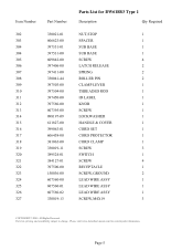
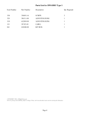
Parts list, pricing, and availability subject to change. Page 6 Item Number 328 329 330 331 861 Part Number 330019-16 396311-00 612054-00 397451-01 618800-00 Parts List for current parts information. All Rights Reserved. Please visit www.dewaltservicenet.com for DW618B3 Type 1 Description Qty Required SCREW 2 ADJUSTING RING 1 ADJUSTING RING 1 LABEL 1 KIT BOX 1 COPYRIGHT© 2005.
Parts list, pricing, and availability subject to change. Page 6 Item Number 328 329 330 331 861 Part Number 330019-16 396311-00 612054-00 397451-01 618800-00 Parts List for current parts information. All Rights Reserved. Please visit www.dewaltservicenet.com for DW618B3 Type 1 Description Qty Required SCREW 2 ADJUSTING RING 1 ADJUSTING RING 1 LABEL 1 KIT BOX 1 COPYRIGHT© 2005.


