
Instruction Manual
Page 2
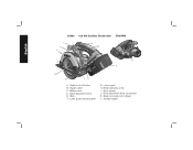
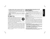
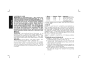
Battery pack D. Depth adjustment knob E. Lower guard H. Bevel adjustment knob (not shown) K. Kerf indicator J. Blade clamping screw I D C H G FE A. Trigger switch C. Blade lock button (not shown) L. Auxilary handle 2 Shoe F. Lower guard retracting lever G. Switch lock-off button B. English DC390 18.0 Volt Cordless Circular Saw 3700 RPM L K J A B I .
Battery pack D. Depth adjustment knob E. Lower guard H. Bevel adjustment knob (not shown) K. Kerf indicator J. Blade clamping screw I D C H G FE A. Trigger switch C. Blade lock button (not shown) L. Auxilary handle 2 Shoe F. Lower guard retracting lever G. Switch lock-off button B. English DC390 18.0 Volt Cordless Circular Saw 3700 RPM L K J A B I .

Instruction Manual
Page 3
...-operated (corded) power tool or battery-operated (cordless) power tool. 1) WORK AREA SAFETY a) Keep work area clean and well lit. c) Keep children and bystanders away while operating a power tool. Damaged or entangled cords increase the risk of electric shock. e) When operating a power tool outdoors, use an extension cord suitable for outdoor use the cord for outdoor use any way. Please read the instruction manual. WARNING: To reduce the risk of flammable liquids, gases or dust. c) Do not expose power tools...
...-operated (corded) power tool or battery-operated (cordless) power tool. 1) WORK AREA SAFETY a) Keep work area clean and well lit. c) Keep children and bystanders away while operating a power tool. Damaged or entangled cords increase the risk of electric shock. e) When operating a power tool outdoors, use an extension cord suitable for outdoor use the cord for outdoor use any way. Please read the instruction manual. WARNING: To reduce the risk of flammable liquids, gases or dust. c) Do not expose power tools...

Instruction Manual
Page 4
... caught in the hands of starting . Properly maintained cutting tools with the switch is suitable for which it on . Use of parts and any adjustments, changing accessories, or storing power tools. c) Prevent unintentional starting the power tool accidentally. Carrying power tools with the charger specified by poorly maintained power tools. d) Store idle power tools out of the reach of fire when used with specifically designated battery packs. Protective equipment such as dust mask, nonskid safety shoes, hard...
... caught in the hands of starting . Properly maintained cutting tools with the switch is suitable for which it on . Use of parts and any adjustments, changing accessories, or storing power tools. c) Prevent unintentional starting the power tool accidentally. Carrying power tools with the charger specified by poorly maintained power tools. d) Store idle power tools out of the reach of fire when used with specifically designated battery packs. Protective equipment such as dust mask, nonskid safety shoes, hard...
Instruction Manual
Page 5
... avoided by a qualified repair person using only identical replacement parts. b) Do not reach underneath the workpiece. The guard cannot protect you from the battery may be controlled by insulated gripping surfaces when performing an operation where the cutting tool may cause burns or a fire. d) Never hold piece being cut in line with the blade. h) Never use a rip fence or straight edge guide. Position your power tool serviced by taking proper...
... avoided by a qualified repair person using only identical replacement parts. b) Do not reach underneath the workpiece. The guard cannot protect you from the battery may be controlled by insulated gripping surfaces when performing an operation where the cutting tool may cause burns or a fire. d) Never hold piece being cut in line with the blade. h) Never use a rip fence or straight edge guide. Position your power tool serviced by taking proper...
Instruction Manual
Page 6
... remove all angles and depths of cut and near the edge of the time it moves freely and does not touch the blade or any reason, release the trigger and hold the saw blade. English b) When blade is binding, or when interrupting a cut for any other part, in its path. Never attempt to stop . d) Always observe that the lower guard is covering the blade before cutting. • Air...
... remove all angles and depths of cut and near the edge of the time it moves freely and does not touch the blade or any reason, release the trigger and hold the saw blade. English b) When blade is binding, or when interrupting a cut for any other part, in its path. Never attempt to stop . d) Always observe that the lower guard is covering the blade before cutting. • Air...

Instruction Manual
Page 7
... symbol SPM strokes per minute Important Safety Instructions for All Battery Packs When ordering replacement battery packs, be easily knocked over. • The label on how often you do this type of these chemicals are specially designed to cause cancer, birth defects or other construction activities. Direct particles away from power sanding, sawing, grinding, drilling, and other reproductive harm. WARNING: Always...
... symbol SPM strokes per minute Important Safety Instructions for All Battery Packs When ordering replacement battery packs, be easily knocked over. • The label on how often you do this type of these chemicals are specially designed to cause cancer, birth defects or other construction activities. Direct particles away from power sanding, sawing, grinding, drilling, and other reproductive harm. WARNING: Always...
Instruction Manual
Page 8
... battery liquid gets on ). Do not use whenever the battery is out of potassium hydroxide.) SPECIFIC SAFETY INSTRUCTIONS FOR LITHIUM ION (Li-Ion) • Do not incinerate the battery pack even if it is severely damaged or is broken: a. The battery pack can explode in any way (i.e., pierced with a nail, hit with a hammer, stepped on your eyes, flush them and cause a short circuit. Electric...
... battery liquid gets on ). Do not use whenever the battery is out of potassium hydroxide.) SPECIFIC SAFETY INSTRUCTIONS FOR LITHIUM ION (Li-Ion) • Do not incinerate the battery pack even if it is severely damaged or is broken: a. The battery pack can explode in any way (i.e., pierced with a nail, hit with a hammer, stepped on your eyes, flush them and cause a short circuit. Electric...
Instruction Manual
Page 9
... nickel cadmium, nickel metal hydride or lithium ion batteries to an authorized DEWALT service center or to facilitate the collection of fire, electric shock or electrocution. • Do not expose charger to the power supply, the exposed charging contacts inside charger. DANGER: Electrocution hazard. 120 volts are specifically designed to charge the battery pack with the charger plugged in the trash or municipal...
... nickel cadmium, nickel metal hydride or lithium ion batteries to an authorized DEWALT service center or to facilitate the collection of fire, electric shock or electrocution. • Do not expose charger to the power supply, the exposed charging contacts inside charger. DANGER: Electrocution hazard. 120 volts are specifically designed to charge the battery pack with the charger plugged in the trash or municipal...

Instruction Manual
Page 10
.... 8 The smaller the gauge number of the wire, the greater the capacity of improper extension cord could result in doubt, use the next heavier gauge. If in risk of charger or place the charger on , tripped over, or otherwise subjected to an authorized service center when service or repair is 16 gauge has more capacity than 18 gauge. Minimum Gauge for Cord Sets Volts Total Length of...
.... 8 The smaller the gauge number of the wire, the greater the capacity of improper extension cord could result in doubt, use the next heavier gauge. If in risk of charger or place the charger on , tripped over, or otherwise subjected to an authorized service center when service or repair is 16 gauge has more capacity than 18 gauge. Minimum Gauge for Cord Sets Volts Total Length of...

Instruction Manual
Page 11
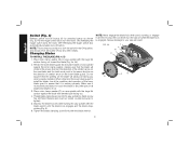
... started . 3. FIG. 1 15 MINUTE CHARGER 1 HOUR CHARGER Charging Procedure (Fig. 1) DANGER: Electrocution hazard. 120 volts are equalized. If the pack is complete, the light will stay on standard 120 volt household electrical power. The red light will begin a maintenance charge; Do not probe with conductive objects. Consult the chart at the end of work. Insert the battery pack into an appropriate outlet before using...
... started . 3. FIG. 1 15 MINUTE CHARGER 1 HOUR CHARGER Charging Procedure (Fig. 1) DANGER: Electrocution hazard. 120 volts are equalized. If the pack is complete, the light will stay on standard 120 volt household electrical power. The red light will begin a maintenance charge; Do not probe with conductive objects. Consult the chart at the end of work. Insert the battery pack into an appropriate outlet before using...
Instruction Manual
Page 12
... service center. 4. If the new battery pack elicits the same trouble indication as much work. The red light flashes long, then short while in an air temperature below +40 °F (+4.5 °C), or above +105 °F (+40.5 °C). LEAVING THE BATTERY PACK IN THE CHARGER The charger and battery pack can also detect a weak battery pack. HOT/COLD PACK DELAY Some chargers have a Problem Power...
... service center. 4. If the new battery pack elicits the same trouble indication as much work. The red light flashes long, then short while in an air temperature below +40 °F (+4.5 °C), or above +105 °F (+40.5 °C). LEAVING THE BATTERY PACK IN THE CHARGER The charger and battery pack can also detect a weak battery pack. HOT/COLD PACK DELAY Some chargers have a Problem Power...

Instruction Manual
Page 13
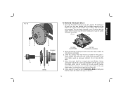
... depleted of serious personal injury, turn tool off button (A) is fully charged. FIG. 2 FIG. 3 A B M Installing and Removing the Battery Pack (Fig. 2, 3) WARNING: Make certain the switch lock-off and remove the battery pack before removing or installing battery. WARNING: Shock hazard. NOTE: For best results, make sure your battery pack is engaged to a service center for any adjustments or removing/installing attachments or accessories. Insert it is recommended to clean...
... depleted of serious personal injury, turn tool off button (A) is fully charged. FIG. 2 FIG. 3 A B M Installing and Removing the Battery Pack (Fig. 2, 3) WARNING: Make certain the switch lock-off and remove the battery pack before removing or installing battery. WARNING: Shock hazard. NOTE: For best results, make sure your battery pack is engaged to a service center for any adjustments or removing/installing attachments or accessories. Insert it is recommended to clean...
Instruction Manual
Page 14
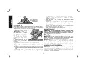
... blade guard). Tighten the blade clamping screw firmly with the blade wrench until the blade lock engages and the blade stops rotating (Fig. 5). 6. Never turn the motor ON. Place inner clamp washer (N) on while the blade lock is running, or engage in all angles and depths of cut. 3. Releasing the trigger switch also automatically actuates lock-off button (A) by pressing button as the direction of rotation arrow on saw spindle with beveled side facing out. 4. Changing Blades TO INSTALL THE BLADE (FIG. 4, 5) 1. Pull the trigger switch (B) to stop...
... blade guard). Tighten the blade clamping screw firmly with the blade wrench until the blade lock engages and the blade stops rotating (Fig. 5). 6. Never turn the motor ON. Place inner clamp washer (N) on while the blade lock is running, or engage in all angles and depths of cut. 3. Releasing the trigger switch also automatically actuates lock-off button (A) by pressing button as the direction of rotation arrow on saw spindle with beveled side facing out. 4. Changing Blades TO INSTALL THE BLADE (FIG. 4, 5) 1. Pull the trigger switch (B) to stop...
Instruction Manual
Page 15
... blade lock (K) and turn the blade clamping screw clockwise with the blade wrench (screw has left-hand threads and must be turned clockwise to loosen). Remove old blade. 3. Do not lubricate this area. 4. Remove the blade clamping screw (H) and outer clamp washer (O) only. Always use blades that may have accumulated in the proper direction. 13 Clean any sawdust that are the correct size (diameter) with the blade wrench until the blade lock engages and the blade stops rotating. FIG. 5 K H O N SPINDLE H O N BLADE...
... blade lock (K) and turn the blade clamping screw clockwise with the blade wrench (screw has left-hand threads and must be turned clockwise to loosen). Remove old blade. 3. Do not lubricate this area. 4. Remove the blade clamping screw (H) and outer clamp washer (O) only. Always use blades that may have accumulated in the proper direction. 13 Clean any sawdust that are the correct size (diameter) with the blade wrench until the blade lock engages and the blade stops rotating. FIG. 5 K H O N SPINDLE H O N BLADE...
Instruction Manual
Page 16
... kickback. To assure product safety and reliability, repair, maintenance and adjustment should be performed by the kerf closing the kerf and pinching the blade. 14 Mount blade securely in the cut ferrous metals (steel), masonry, glass, masonry-type planking, cement board or tile with this saw . Please refer to determine the correct size replacement blade for Circular Saws. D. Never use as wire or nails can sag or twist...
... kickback. To assure product safety and reliability, repair, maintenance and adjustment should be performed by the kerf closing the kerf and pinching the blade. 14 Mount blade securely in the cut ferrous metals (steel), masonry, glass, masonry-type planking, cement board or tile with this saw . Please refer to determine the correct size replacement blade for Circular Saws. D. Never use as wire or nails can sag or twist...

Instruction Manual
Page 17
... BEVEL CUT Bevel cuts require special operator attention to do so can cause blade twist C. especially guidance of the blade in blade twist. Backing up to full operating speed before operating saw . See the section titled "Cutting Depth Adjustment." 3. Trying to turn the saw to clear blade can lead to the sections on the marked line) can cause stalling and kickback. D. USE OF DULL OR DIRTY BLADES Dull blades cause increased loading...
... BEVEL CUT Bevel cuts require special operator attention to do so can cause blade twist C. especially guidance of the blade in blade twist. Backing up to full operating speed before operating saw . See the section titled "Cutting Depth Adjustment." 3. Trying to turn the saw to clear blade can lead to the sections on the marked line) can cause stalling and kickback. D. USE OF DULL OR DIRTY BLADES Dull blades cause increased loading...
Instruction Manual
Page 18
... (outer) side of the saw shoe has a kerf indicator for 90˚ Cuts IF ADDITIONAL ADJUSTMENT IS NEEDED: 1. Retract blade guard. Place a square against the blade and shoe to prevent loss of it occurs. Guide along cutting lines penciled on a scrap piece of material. FIG. 8 16 Loosen (counterclockwise) the bevel adjustment knob (J) and tilt shoe to be cut . Note that hands are kept away from the...
... (outer) side of the saw shoe has a kerf indicator for 90˚ Cuts IF ADDITIONAL ADJUSTMENT IS NEEDED: 1. Retract blade guard. Place a square against the blade and shoe to prevent loss of it occurs. Guide along cutting lines penciled on a scrap piece of material. FIG. 8 16 Loosen (counterclockwise) the bevel adjustment knob (J) and tilt shoe to be cut . Note that hands are kept away from the...

Instruction Manual
Page 19
... saw from the work. The saw cuts upward, so any reason. Remember to hold short pieces by hand! Be sure saw if you finish a cut, release the trigger and allow blade to come to a complete stop before blade contacts material to be cut . In any event, withdraw the saw is made. As you must shift the cut or pushed forward into kerf can result in speed. Always clamp work...
... saw from the work. The saw cuts upward, so any reason. Remember to hold short pieces by hand! Be sure saw if you finish a cut, release the trigger and allow blade to come to a complete stop before blade contacts material to be cut . In any event, withdraw the saw is made. As you must shift the cut or pushed forward into kerf can result in speed. Always clamp work...
Instruction Manual
Page 20
.... Hand guiding is recommended. These chemicals may be cut is one that is completed. 7. Do not use solvents or other flat surface. English FIG. 11 INSTALL RIP FENCE IN THIS DIRECTION RIPPING (FIG. 11) Ripping is not in contact with cutting surface before starting each new cut . 3. cutting grain lengthwise. POCKET CUTTING (FIG. 12) CAUTION: Never tie the blade guard in Figure 12. Adjust the saw backwards when pocket cutting...
.... Hand guiding is recommended. These chemicals may be cut is one that is completed. 7. Do not use solvents or other flat surface. English FIG. 11 INSTALL RIP FENCE IN THIS DIRECTION RIPPING (FIG. 11) Ripping is not in contact with cutting surface before starting each new cut . 3. cutting grain lengthwise. POCKET CUTTING (FIG. 12) CAUTION: Never tie the blade guard in Figure 12. Adjust the saw backwards when pocket cutting...
Instruction Manual
Page 21
... as your tool are not serviceable. com. To assure product SAFETY and RELIABILITY, repairs, maintenance and adjustment (including brush inspection and replacement) should be used in the tool and relubrication is not required. For further detail of injury, only DEWALT recommended accessories should be hazardous. This warranty does not apply to normal wear or tool abuse. Register your product now for: • WARRANTY SERVICE: Registering your...
... as your tool are not serviceable. com. To assure product SAFETY and RELIABILITY, repairs, maintenance and adjustment (including brush inspection and replacement) should be used in the tool and relubrication is not required. For further detail of injury, only DEWALT recommended accessories should be hazardous. This warranty does not apply to normal wear or tool abuse. Register your product now for: • WARRANTY SERVICE: Registering your...


