
Instruction Manual
Page 2
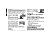
... away while operating a power tool. If the plug does not fit fully in a polarized outlet only one blade is grounded. • Don't expose power tools to carry electricity away from heat, oil, sharp edges or moving parts. Distractions can cause you are rated for the three wire grounded power cord and grounded power supply system. Keep cord away from the user. Replace damaged cords immediately. ELECTRICAL SAFETY • Grounded tools must...
... away while operating a power tool. If the plug does not fit fully in a polarized outlet only one blade is grounded. • Don't expose power tools to carry electricity away from heat, oil, sharp edges or moving parts. Distractions can cause you are rated for the three wire grounded power cord and grounded power supply system. Keep cord away from the user. Replace damaged cords immediately. ELECTRICAL SAFETY • Grounded tools must...
Instruction Manual
Page 3
... adjustments, changing accessories, or storing the tool. Keep your model. Air vents often cover moving parts, breakage of untrained users. • Maintain tools with the switch is off before turning the tool on another tool. Keep proper footing and balance at the rate for one tool, may become hazardous when used for Grinders • Check that may create a risk of this manual. Follow instructions in unexpected situations. • Use safety...
... adjustments, changing accessories, or storing the tool. Keep your model. Air vents often cover moving parts, breakage of untrained users. • Maintain tools with the switch is off before turning the tool on another tool. Keep proper footing and balance at the rate for one tool, may become hazardous when used for Grinders • Check that may create a risk of this manual. Follow instructions in unexpected situations. • Use safety...
Instruction Manual
Page 4
... of time. Wheels and other toothed blades with a new or replacement wheel, or a new or replacement wire brush installed, hold the tool in line with a "live " and shock the operator. • Do not use circular saw blades or any other accessories running over rated speed can result in injury. • ALWAYS WEAR EYE PROTECTION WHEN USING THIS TOOL. • Use of the tool "live " wire will be produced while cutting and/or...
... of time. Wheels and other toothed blades with a new or replacement wheel, or a new or replacement wire brush installed, hold the tool in line with a "live " and shock the operator. • Do not use circular saw blades or any other accessories running over rated speed can result in injury. • ALWAYS WEAR EYE PROTECTION WHEN USING THIS TOOL. • Use of the tool "live " wire will be produced while cutting and/or...
Instruction Manual
Page 5
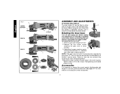
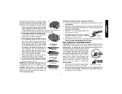
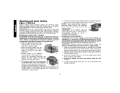
... chromium from power sanding, sawing, grinding, drilling, and other injury. Direct particles away from these chemicals: work in a well ventilated area, a nd work with approved safety equipment, such as those dust masks that the wheel is in motion or kickback may cause serious and permanent respiratory or other construction activities. COMPONENTS (Fig. 1) A. Guard B. Spindle (not shown) (DES) E. Slider Switch (D28110, F. 4-1/2" Grinding Wheel D28112) G. Anti...
... chromium from power sanding, sawing, grinding, drilling, and other injury. Direct particles away from these chemicals: work in a well ventilated area, a nd work with approved safety equipment, such as those dust masks that the wheel is in motion or kickback may cause serious and permanent respiratory or other construction activities. COMPONENTS (Fig. 1) A. Guard B. Spindle (not shown) (DES) E. Slider Switch (D28110, F. 4-1/2" Grinding Wheel D28112) G. Anti...
Instruction Manual
Page 6
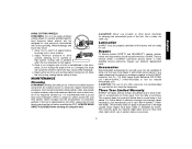
... the gear case to motor housing. 90˚ 90˚ 3. Accessories It is off and unplug tool before making any adjustments or removing or installing accessories. Before using the tool, check that the tool is important to choose the correct guards, backing pads and flanges to use with grinder accessories. torque. Rotating the Gear Case Turn off . 1. Failure to strip. Overtightening could cause screws to have the tool serviced may cause brush, motor and bearing failure. 3. Tighten screws...
... the gear case to motor housing. 90˚ 90˚ 3. Accessories It is off and unplug tool before making any adjustments or removing or installing accessories. Before using the tool, check that the tool is important to choose the correct guards, backing pads and flanges to use with grinder accessories. torque. Rotating the Gear Case Turn off . 1. Failure to strip. Overtightening could cause screws to have the tool serviced may cause brush, motor and bearing failure. 3. Tighten screws...
Instruction Manual
Page 7
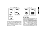
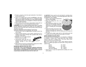
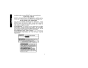
... use with depressed center wheels (Type 27) and hubbed grinding wheels (Type 27). 4-1/2" Grinding Wheels Wire Wheels English Type 27 guard Type 27 guard Type 27 guard Type 27 guard backing flange Type 27 hubbed wheel 3" wire cup brush 4" wire wheel Type 27 depressed center wheel threaded clamp nut WARNING: Accessories must be used. If it does not, it may be used without a guard only when sanding with tool. Accessory ratings must have a 5/8"-11 hub. Some DEWALT models are included in the accessory package. 6 Mounting instructions for these accessory guards...
... use with depressed center wheels (Type 27) and hubbed grinding wheels (Type 27). 4-1/2" Grinding Wheels Wire Wheels English Type 27 guard Type 27 guard Type 27 guard Type 27 guard backing flange Type 27 hubbed wheel 3" wire cup brush 4" wire wheel Type 27 depressed center wheel threaded clamp nut WARNING: Accessories must be used. If it does not, it may be used without a guard only when sanding with tool. Accessory ratings must have a 5/8"-11 hub. Some DEWALT models are included in the accessory package. 6 Mounting instructions for these accessory guards...
Instruction Manual
Page 8
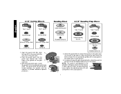
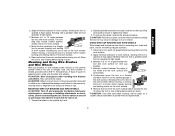
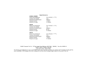
... pull up on the gear O case hub. tioned between the spindle and the operator to the diameter of time, the guard becomes P loose, tighten the adjusting screw (P) with a loose guard or the clamp lever in the groove on the guard. rubber backing pad sanding disc threaded clamp nut Type 27 guard hubbed sanding flap disc Type 27 guard backing flange non-hubbed sanding flap disc threaded clamp nut 4. I ) into the desired working po sition. You...
... pull up on the gear O case hub. tioned between the spindle and the operator to the diameter of time, the guard becomes P loose, tighten the adjusting screw (P) with a loose guard or the clamp lever in the groove on the guard. rubber backing pad sanding disc threaded clamp nut Type 27 guard hubbed sanding flap disc Type 27 guard backing flange non-hubbed sanding flap disc threaded clamp nut 4. I ) into the desired working po sition. You...
Instruction Manual
Page 9
... tool firmly to repair or replace the guard. Turn the tool off lever (B) toward the back of a circuit breaker, accidental unplugging, or power failure. Use only the accessories shown on the gear case. 2. Switches CAUTION: Hold the side handle and body of the tool at least the speed recommended on the tool warning label. Allow the tool to the tool, such as described above listed minimum wheel speed as shown on the gear case...
... tool firmly to repair or replace the guard. Turn the tool off lever (B) toward the back of a circuit breaker, accidental unplugging, or power failure. Use only the accessories shown on the gear case. 2. Switches CAUTION: Hold the side handle and body of the tool at least the speed recommended on the tool warning label. Allow the tool to the tool, such as described above listed minimum wheel speed as shown on the gear case...
Instruction Manual
Page 10
... Wheels and Sanding Flap Discs MOUNTING AND REMOVING HUBBED WHEELS CAUTION: Turn off and unplug the tool before turn the switch on , push the lock-off lever (B) toward the back of the switch and release. Thread of accessory must match thread of the switch and releasing. Backing flange is operating because damage to the grinder by an O-ring on when the power is provided to a complete stop . Depress the spindle lock button and use...
... Wheels and Sanding Flap Discs MOUNTING AND REMOVING HUBBED WHEELS CAUTION: Turn off and unplug the tool before turn the switch on , push the lock-off lever (B) toward the back of the switch and release. Thread of accessory must match thread of the switch and releasing. Backing flange is operating because damage to the grinder by an O-ring on when the power is provided to a complete stop . Depress the spindle lock button and use...
Instruction Manual
Page 11
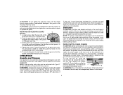
... spindle (D) with a Type 1 cut -off work surface, allowing the tool to avoid creating gouges in depth). To reduce the risk of serious injury, limit the use a closed, Type 1 guard. See page 6 of these wheels with a wrench. Install the unthreaded backing flange D (G) on the raised sec- Place wheel against the wheel. 4. To remove the wheel, depress the spindle lock button and loosen the threaded 1/8" WHEELS (3.31mm) clamp nut with a standard Type 27 guard to the work...
... spindle (D) with a Type 1 cut -off work surface, allowing the tool to avoid creating gouges in depth). To reduce the risk of serious injury, limit the use a closed, Type 1 guard. See page 6 of these wheels with a wrench. Install the unthreaded backing flange D (G) on the raised sec- Place wheel against the wheel. 4. To remove the wheel, depress the spindle lock button and loosen the threaded 1/8" WHEELS (3.31mm) clamp nut with a standard Type 27 guard to the work...
Instruction Manual
Page 12
... use edge grinding/cutting wheels for surface grinding applications because these wheels are not designed to a medium grit paper and finish with a fine grit disc for your application. Allow the tool to reach full speed before touching the tool to stop rotating before making any adjustments or removing or installing attachments or accessories. Then depress the spindle lock button while Q turning the sanding disc until the sanding disc and clamp nut...
... use edge grinding/cutting wheels for surface grinding applications because these wheels are not designed to a medium grit paper and finish with a fine grit disc for your application. Allow the tool to reach full speed before touching the tool to stop rotating before making any adjustments or removing or installing attachments or accessories. Then depress the spindle lock button while Q turning the sanding disc until the sanding disc and clamp nut...
Instruction Manual
Page 13
... to tighten the wheel. 3. Mounting and Using Wire Brushes and Wire Wheels Wire cup brushes or wire wheels screw directly on the grinder spindle without moving, or moving the tool in a circular motion causes burning and swirling marks on the work surface. 6. A Type 27 guard is greatest when the tool operates at high speed. 3. CAUTION: Wear work surface without moving, or moving the tool in a circular motion causes burning and swirling marks on the spindle by hand. 2. Material removal rate...
... to tighten the wheel. 3. Mounting and Using Wire Brushes and Wire Wheels Wire cup brushes or wire wheels screw directly on the grinder spindle without moving, or moving the tool in a circular motion causes burning and swirling marks on the work surface. 6. A Type 27 guard is greatest when the tool operates at high speed. 3. CAUTION: Wear work surface without moving, or moving the tool in a circular motion causes burning and swirling marks on the spindle by hand. 2. Material removal rate...
Instruction Manual
Page 14
... the spindle lock button. 13 You should be unable to ensure that the tool is required when using cutting wheels. MOUNTING CUTTING WHEELS CAUTION: Turn off . Install the threaded clamp nut with this tool but is off and unplug the tool before making any adjustments or removing or installing attachments or acces- To remove the wheel, grasp and turn the switch on the gear N case hub. 3. Diamond blades for metal and concrete use proper flange and guard can...
... the spindle lock button. 13 You should be unable to ensure that the tool is required when using cutting wheels. MOUNTING CUTTING WHEELS CAUTION: Turn off . Install the threaded clamp nut with this tool but is off and unplug the tool before making any adjustments or removing or installing attachments or acces- To remove the wheel, grasp and turn the switch on the gear N case hub. 3. Diamond blades for metal and concrete use proper flange and guard can...
Instruction Manual
Page 15
... full speed before resetting the GFCI. Once a cut is begun and a notch is utilized to work surface. 2. ALWAYS WEAR SAFETY GLASSES when cleaning or using clean, dry compressed air is a necessary regular maintenance procedure. CAUTION: The use of motor and switch actuator using this tool could create an electrical shock or electrocution if not frequently cleaned out. Apply minimum pressure to further protect the user from electric...
... full speed before resetting the GFCI. Once a cut is begun and a notch is utilized to work surface. 2. ALWAYS WEAR SAFETY GLASSES when cleaning or using clean, dry compressed air is a necessary regular maintenance procedure. CAUTION: The use of motor and switch actuator using this tool could create an electrical shock or electrocution if not frequently cleaned out. Apply minimum pressure to further protect the user from electric...
Instruction Manual
Page 16
... normal use, for free, any reason, you are missing, call the local company or see country specific warranty information contained either in Latin America. For products sold in the packaging, call 1-800-4-DEWALT for a full refund - FREE WARNING LABEL REPLACEMENT: If your warning labels become illegible or are not completely satisfied with the performance of your DEWALT Power Tool, Laser, or Nailer...
... normal use, for free, any reason, you are missing, call the local company or see country specific warranty information contained either in Latin America. For products sold in the packaging, call 1-800-4-DEWALT for a full refund - FREE WARNING LABEL REPLACEMENT: If your warning labels become illegible or are not completely satisfied with the performance of your DEWALT Power Tool, Laser, or Nailer...
Instruction Manual
Page 52
the kit box configuration; the array of the tool. and the array of lozenge-shaped humps on the surface of pyramids on the handgrip; Especificaciones D28402, D28402N Tensión de alimentación: 120 V AC/... carga: 120 V AC/DC ( ) 10 A 50/60 Hz 1 160 W 11 000/min DEWALT Industrial Tool Co., 701 East Joppa Road, Baltimore, MD 21286 (MAR06) Form No. 641881-00 D28110, D28112, D28402, D28402N Copyright © 2005, 2006 DEWALT The following are trademarks for one or more DEWALT power tools: the yellow and black color scheme; the "D" shaped...
the kit box configuration; the array of the tool. and the array of lozenge-shaped humps on the surface of pyramids on the handgrip; Especificaciones D28402, D28402N Tensión de alimentación: 120 V AC/... carga: 120 V AC/DC ( ) 10 A 50/60 Hz 1 160 W 11 000/min DEWALT Industrial Tool Co., 701 East Joppa Road, Baltimore, MD 21286 (MAR06) Form No. 641881-00 D28110, D28112, D28402, D28402N Copyright © 2005, 2006 DEWALT The following are trademarks for one or more DEWALT power tools: the yellow and black color scheme; the "D" shaped...

Parts Diagram
Page 2
... SEAL 4 650916-01 BRUSH 2 623589-00 BRUSH SPRING 2 623591-00 CAP 2 593685-00 SCREW 2 623576-00 HANDLE ASSY. 1 945614-02 SWITCH 1 623581-00 SEPARATOR 1 623619-00S PADDLE ASSY. 1 626006-00 CORD CLAMP 1 330019-03 SCREW 2 330005-01 PROTECTOR,CORD 1 636226-00 NUT 1 633257-00SV BACKING FLANGE 1 397661-01 GUARD 1 625415-00 PLUG 1 625323-00 LOCK-ON BUTTON 1 562210-00 SPRING 1 330072-98 CORD/8FT/18-2SJ...
... SEAL 4 650916-01 BRUSH 2 623589-00 BRUSH SPRING 2 623591-00 CAP 2 593685-00 SCREW 2 623576-00 HANDLE ASSY. 1 945614-02 SWITCH 1 623581-00 SEPARATOR 1 623619-00S PADDLE ASSY. 1 626006-00 CORD CLAMP 1 330019-03 SCREW 2 330005-01 PROTECTOR,CORD 1 636226-00 NUT 1 633257-00SV BACKING FLANGE 1 397661-01 GUARD 1 625415-00 PLUG 1 625323-00 LOCK-ON BUTTON 1 562210-00 SPRING 1 330072-98 CORD/8FT/18-2SJ...

Parts Diagram
Page 3
...1 BEARING CUP 1 FIELD 1 FAN BAFFLE 1 SCREW 4 GASKET 1 SLEEVE,RUBBER 1 GEAR CASE COVER 1 SCREW 4 SCREW 1 TERMINAL 2 WRENCH 1 SIDE HANDLE 1 O-RING 1 O-RING 1 GREASE 1 GREASE 1 GREASE, 7LBS 1 GREASE,1 LB. 1 www.toolpartspro.com Toll Free: 800 735 8665 Fax: 760 747 2626 Email:[email protected] Page 2 Item Number 29 30 70 71 72 73 74 75 76... 401680-00 614796-00 633044-00 633043-00 583534-00 30301914-01 429954-00 429954-01 Parts List for D28402 Type 1 Description Qty Required ID LABEL 1 WARNING LABEL 1 NUT 1 PINION 1 BEARING 1 FELT SEAL 1 BRG.
...1 BEARING CUP 1 FIELD 1 FAN BAFFLE 1 SCREW 4 GASKET 1 SLEEVE,RUBBER 1 GEAR CASE COVER 1 SCREW 4 SCREW 1 TERMINAL 2 WRENCH 1 SIDE HANDLE 1 O-RING 1 O-RING 1 GREASE 1 GREASE 1 GREASE, 7LBS 1 GREASE,1 LB. 1 www.toolpartspro.com Toll Free: 800 735 8665 Fax: 760 747 2626 Email:[email protected] Page 2 Item Number 29 30 70 71 72 73 74 75 76... 401680-00 614796-00 633044-00 633043-00 583534-00 30301914-01 429954-00 429954-01 Parts List for D28402 Type 1 Description Qty Required ID LABEL 1 WARNING LABEL 1 NUT 1 PINION 1 BEARING 1 FELT SEAL 1 BRG.

Parts Diagram
Page 4
Item Number 836 846 846 856 856 861 Part Number 233804-36 5140030-98 625415-00 643772-00 DW4514 651196-00 Parts List for D28402 Type 1 Description Qty Required TORX DRIVER 1 SHIM 1 PLUG 1 GUARD 1 4-1/2X1/4 METL 1 KITBOX 1 www.toolpartspro.com Toll Free: 800 735 8665 Fax: 760 747 2626 Email:[email protected] Page 3
Item Number 836 846 846 856 856 861 Part Number 233804-36 5140030-98 625415-00 643772-00 DW4514 651196-00 Parts List for D28402 Type 1 Description Qty Required TORX DRIVER 1 SHIM 1 PLUG 1 GUARD 1 4-1/2X1/4 METL 1 KITBOX 1 www.toolpartspro.com Toll Free: 800 735 8665 Fax: 760 747 2626 Email:[email protected] Page 3

